Method and apparatus for measuring magnetic offset of geomagnetic sensor and portable electronic apparatus

Inactive Publication Date: 2005-12-29
YAMAHA CORP
View PDF9 Cites 58 Cited by
  • Summary
  • Abstract
  • Description
  • Claims
  • Application Information

AI Technical Summary

Benefits of technology

[0027] Therefore, the present invention has been made in consideration of the foregoing circumstances and has an object to provide a geomagnetic sensor correction method that corrects an offset caused by magnetization, for example, only by swinging a geom

Problems solved by technology

As a result, there have been instances where, in a portable telephone that detects the geomagnetism by a geomagnetic sensor mounted therein, an azimuth calculated on the basis of a magnetic field existing inside the portable telephone does not indicate a correct azimuth.
There has been a problem that it is difficult, in particular, to cause the portable telephone to make one or more turns while keeping it horizontal so that there is a possibility of the portable telephone being dropped once in a while and, even with no occurrence of the portable telephone being dropped, variation occurs in obtained data so that an offset cannot be derived accurately.
Therefore, there has also been a problem that the foregoing conventional geomagnetic sensor correction method is unsuitable for portable devices.
However, although the technique according to this publication can demagnetize, inside the electronic azimuth finder, a magnetic field generated by one, for example, a permanent magnet, that generates a magnetic field in a constant direction with respect to a direction of the electronic azimuth finder regardless of a direction of the geomagnetism, it cannot demagnetize an induction magnetic field that is generated by a soft magnetic

Method used


Image

  • Method and apparatus for measuring magnetic offset of geomagnetic sensor and portable electronic apparatus
  • Method and apparatus for measuring magnetic offset of geomagnetic sensor and portable electronic apparatus
  • Method and apparatus for measuring magnetic offset of geomagnetic sensor and portable electronic apparatus

Examples


second embodiment

[0181] Next, the present invention will be described.

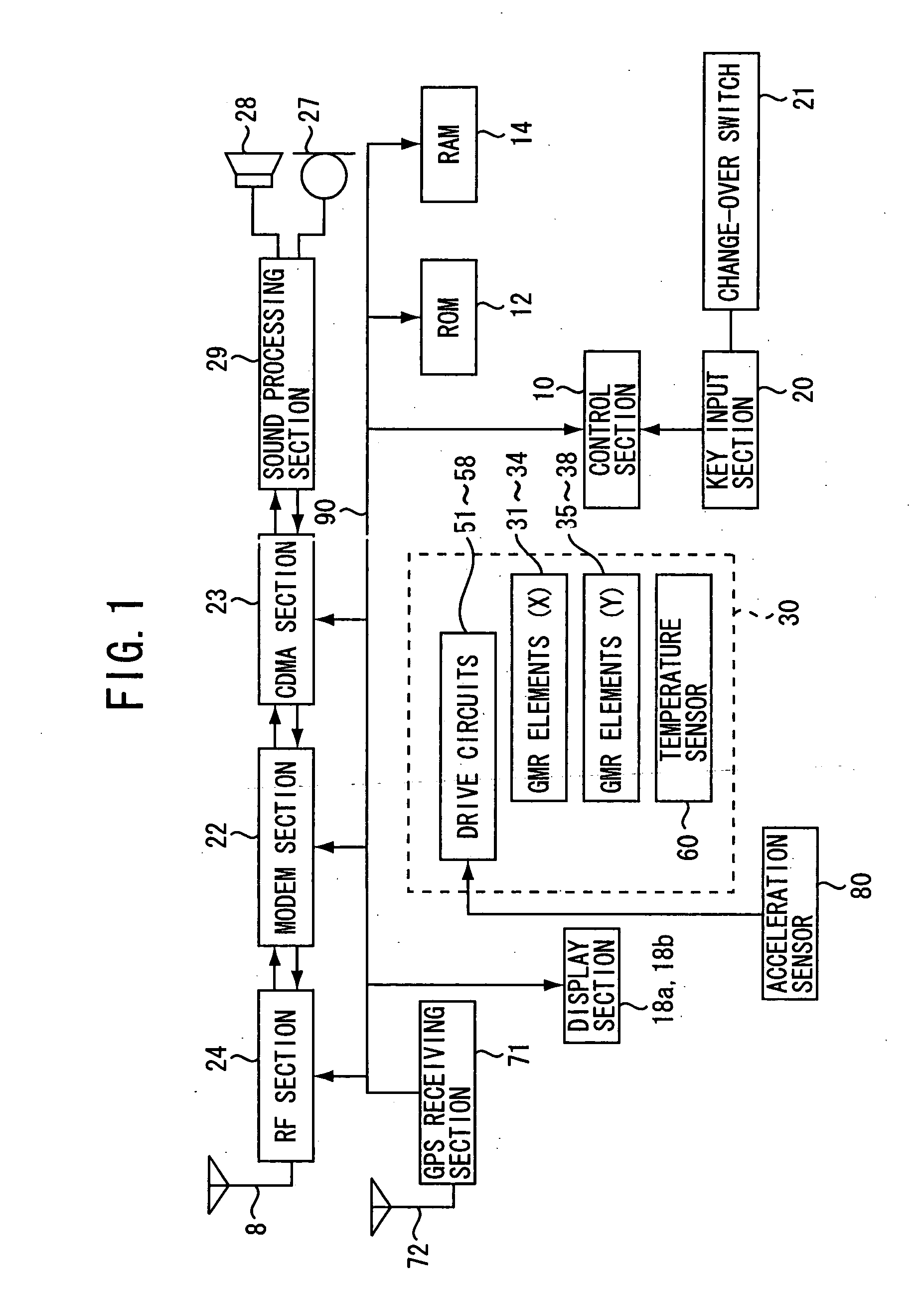
[0182] The block structure of a portable telephone in this second embodiment is the same as that in the first embodiment, but the offset calibration processing of a control section 10 differs from that in the first embodiment. Hereinbelow, this embodiment will be described with reference to the drawing.

[0183] As shown in FIG. 17, the processing of steps Sb1 and Sb2 is carried out. This processing is the same as that of steps Sa1 and Sa2 shown in FIG. 13. Then, the control section 10 reads out the measurement data from a geomagnetic sensor 30 (step Sb3) (data reading means). Then, by judging in step Sb3 whether or not the distance in the coordinate system between the current data and the previous data that has been stored one sample before in the RAM 14 from the geomagnetic sensor 30 exceeds a predetermined distance, it is judged whether or not the current data should be stored into the RAM 14 (step Sb4) (data storage judging mean...

first embodiment

[0188] As described above, according to this embodiment, the following problem can be avoided. Specifically, it is possible to avoid a problem that, in the first embodiment, data is concentrated to the vicinity of a certain point when the data is captured while a user hardly moves the portable telephone, or the speed of moving the portable telephone by a user is not uniform so that the density of data becomes uneven.

[0189] Herein, the number of measurement points is preferably 20 or more when the measurement range is 90° (rotation angle of the geomagnetic sensor) and, therefore, a distance between the measurement points on the coordinate system is required to be smaller than 1 / 10 of the radius of an compass circle. In view of the foregoing, it may be arranged that the processing of reading data from the geomagnetic sensor 30 is not performed per certain time interval, but is performed by rotating the geomagnetic sensor 30 at a rotation angle that makes the distance between the measu...

third embodiment

[0190] Next, the present invention will be described.

[0191] The block structure of a portable telephone in this second embodiment is the same as that in the first or second embodiment, but the offset calibration processing of a control section 10 is a combination of the first and second embodiments. Hereinbelow, this embodiment will be described. Note that a flowchart is a combination of FIGS. 13 and 17 and illustration thereof is omitted.

[0192] In this case, the processing of steps Sa2 to Sa6 in FIG. 13 and the processing of steps Sb2 to Sb7 in FIG. 17 are processed parallelly and, when the number of data stored in the RAM 14 by either one of the processings exceeds a predetermined number, the offset estimation in step Sa7 or Sb8 is carried out. With respect to the predetermined numbers, it is necessary that the number of data by the processing of FIG. 13 be set greater than the number of data by the processing of FIG. 17. For example, it is desirable that the former be set 10 tim...


PUM


Abstract

A method is designed for measuring a magnetic offset of a geomagnetic sensor equipped in a portable information terminal apparatus having a storage. The geomagnetic sensor has a magnetic sensitivity to a geomagnetic field and is affected by magnetization to cause the magnetic offset. In the method, an output of the geomagnetic sensor is measured to successively provide measurement data of the geomagnetic field from the output of the geomagnetic sensor. The measurement data is stored in the storage. The measurement data is read out from the storage when a number of the measurement data stored in the storage reaches a predetermined number, and an offset value of the magnetic offset is estimated based on the predetermined number of the measurement data read out from the storage.

Description

BACKGROUND OF THE INVENTION [0001] 1. Technical Field [0002] The present invention relates to a method and apparatus for measuring a magnetic offset of a geomagnetic sensor equipped in a portable information terminal apparatus. [0003] 2. Background Art [0004] In the case of a conventional geomagnetic sensor, when mounted inside a portable telephone (portable information terminal), because of the presence of magnetic fields leaking from a speaker, a metal package of magnetized electronic components, and so on that are mounted together, the geomagnetic sensor detects even those noise magnetic fields generated by them. As a result, there have been instances where, in a portable telephone that detects the geomagnetism by a geomagnetic sensor mounted therein, an azimuth calculated on the basis of a magnetic field existing inside the portable telephone does not indicate a correct azimuth. [0005] For example, in a portable telephone mounted with a geomagnetic sensor having sensitivity dire...

Claims


Application Information

Patent Timeline
IPC IPC(8): G01C17/38G01D5/244G01D18/00
CPCG01D3/0365G01C17/38G01C17/30G01C25/00H04M2250/12
Inventor SATO, HIDEKINIHASHI, SATOSHI
Owner YAMAHA CORP
Why Eureka
Try Eureka