
Current collector sheet and electrochemical device

a current collector and electrochemical technology, applied in the manufacture of secondary cells, electrode manufacturing processes, final product manufacturing, etc., can solve the problems of increasing the possibility of internal short circuit, limiting the electric capacity of a product already having a certain capacity, and hindering the improvement of battery reliability, etc., to reduce the possibility of short circuit, simplify the current collecting structure, and high reliability

Inactive Publication Date: 2005-12-29
PANASONIC CORP
View PDF11 Cites 34 Cited by
  • Summary
  • Abstract
  • Description
  • Claims
  • Application Information

AI Technical Summary

Benefits of technology

[0010] The present invention is intended to solve the above problems by forming both a conductive area and an insulating area on the surface of a current collector sheet. According to the present invention, it is possible to expose the insulating area without an electrode material mixture carried thereon while an electrode material mixture is carried on the conductive area of a current collector sheet. Such structure greatly reduces the possibility of short-circuiting because a portion of the current collector sheet without an electrode material mixture applied thereon comprises an insulating area. Moreover, the current collecting structure is simplified because the conductive area of the current collector sheet of one electrode and the insulating area of the current collector sheet of another electrode can be alternately arranged at the current collecting area. As described above, according to the present invention, it is possible to provide a highly reliable electrochemical device with a simplified current collecting structure and a high electric capacity. Further, according to the present invention, a plurality of electrochemical devices can be efficiently produced at a time.
[0012] In an embodiment of the present invention, a secondary battery comprising a bipolar electrode with a high capacity capable of achieving size reduction can be provided. Furthermore, according to the present invention, even when a bipolar electrode is used, it is possible to simplify the production process for a spiral type electrode and to greatly reduce the possibility of displacement during winding process.

Problems solved by technology

Secondary batteries currently available, however, have a complicated internal structure so that there is a limit in improving the electric capacity of a product which already has a certain capacity.
The complex structure thereof is partly responsible for hindering the improvement of reliability of the battery.
In addition, internal short-circuiting which occurs in the case where metal burrs larger than normal are left in the cutting plane of the lead is also a matter for concern.
A conventional current collector sheet for carrying an electrode material mixture is accompanied by the problem of an increased possibility of internal short-circuiting because the entire sheet serves as the conductive area and a portion where an electrode material mixture is not applied inevitably possesses conductivity.
Additionally, in the case where a positive electrode is projected from one side face of an electrode assembly and a negative electrode is projected from the other side face opposite to the aforesaid side face, the structure of a current collector will be complicated and therefore it is required to produce electrode assemblies one by one, making the production process of the electrode assembly complicated.
In short, a conventional current collector sheet also has the problem that a plurality of electrode assemblies cannot be produced at one time.
The reason why a bipolar type electrode is not used in a spiral type electrode assembly is because it makes the structure of the electrode assembly complicated.
In order to ensure insulation between electrodes in a spiral type electrode assembly, various measures will be necessary, which will make the structure complicated, so that there is no advantage in using a bipolar type electrode.
This makes its production process complicated, likely to cause problems such as displacement during spiral winding process.

Method used


Image

  • Current collector sheet and electrochemical device
  • Current collector sheet and electrochemical device
  • Current collector sheet and electrochemical device

Examples


embodiment 1

[0094] In this embodiment, a description will be given of a current collector sheet (current collector sheet A) having a conductive area and an insulating area on the surface thereof, wherein the current collector sheet includes an insulating sheet, the conductive area comprises a conductive layer formed on the surface of the insulating sheet and the insulating area comprises an exposed portion of the insulating sheet.

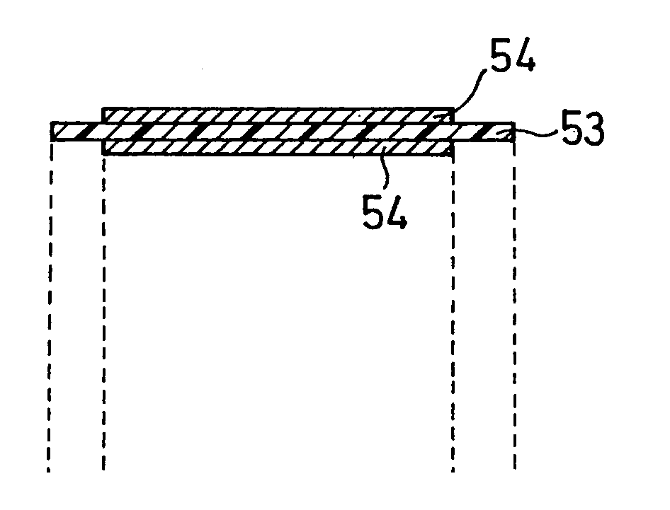
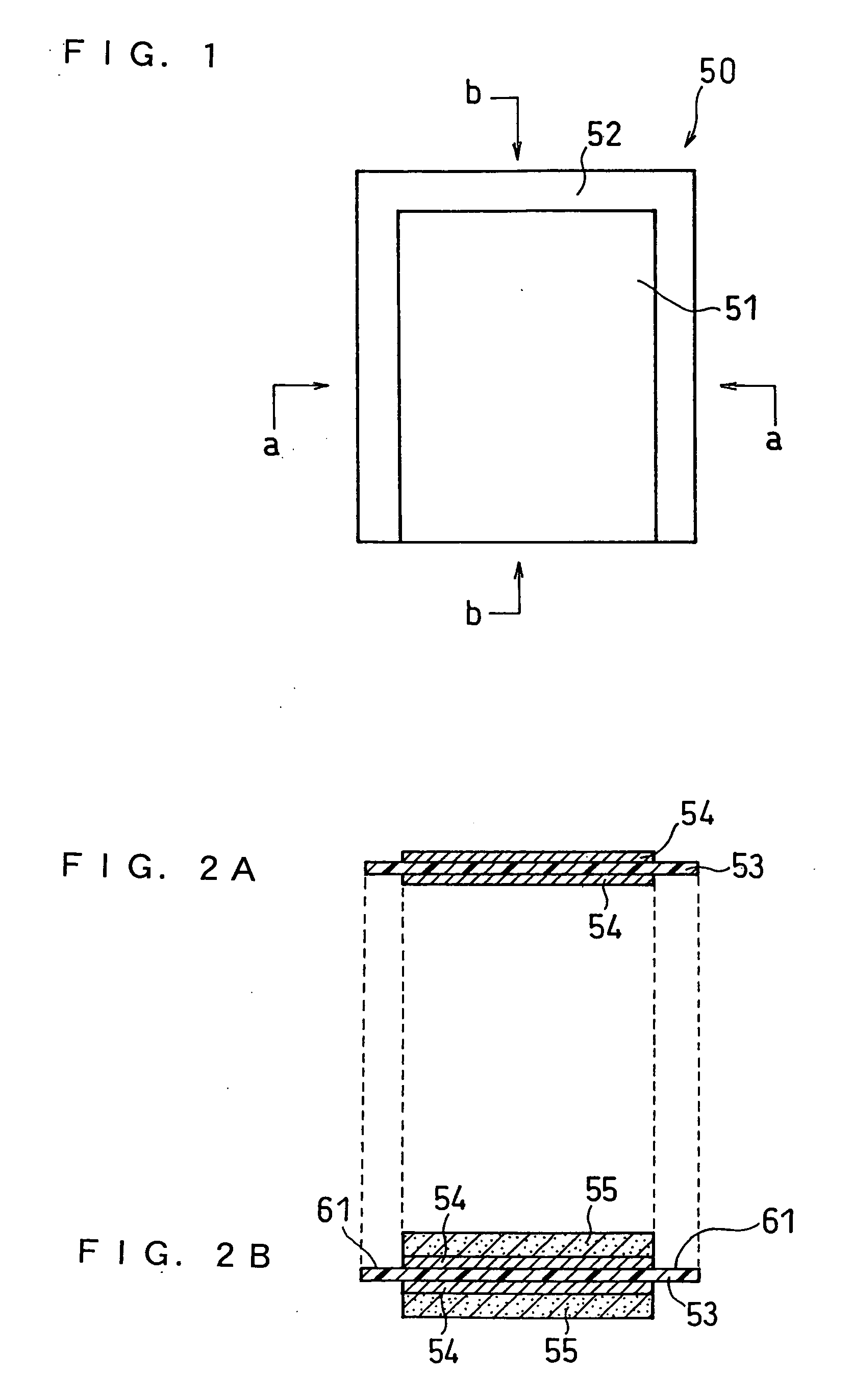
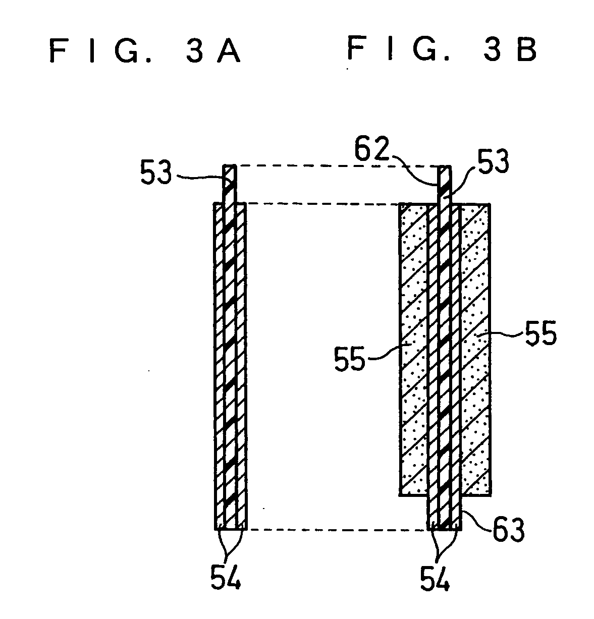
[0095]FIG. 1 is a top plan view of a current collector sheet A50. FIG. 2A is a sectional view taken on line a-a of FIG. 1 of the current collector sheet A. FIG. 3A is a sectional view taken on line b-b of FIG. 1 of the current collector sheet A.

[0096] The current collector sheet A comprises an insulating sheet 53 and a conductive layer 54 formed on each surface of the insulating sheet 53. The surface of the conductive layer 54 serves as the conductive area 51, and an exposed portion of the insulating sheet 53 serves as the insulating area 52.

[0097] Since both conduc...

embodiment 2

[0105] Another embodiment of the current collector sheet A (current collector sheet A′) will now be described.

[0106]FIG. 4 is a top plan view of a current collector sheet A′50′. FIG. 5A is a cross sectional view taken on line a-a of FIG. 4 of the current collector sheet A′. FIG. 6A is a cross sectional view taken on line b-b of FIG. 4 of the current collector sheet A′.

[0107] The current collector sheet A′ comprises an insulating sheet 53′ and a conductive layer 54′ formed on each surface of the insulating sheet 53′. The surface of the conductive layer 54′ serves as the conductive area 51′, and an exposed portion of the insulating sheet 53′ serves as the insulating area 52′.

[0108] For example, when an electrode material mixture 55′ is applied only onto the conductive area 51′, the surface of the insulating sheet will be exposed in electrode material mixture unapplied portions 61′ and 62′ as shown in FIGS. 5B and 6B. The exposed portions are insulative and therefore will not serve ...

embodiment 3

[0112] In this embodiment, a description will be given of a current collector sheet (current collector sheet B) having a conductive area and an insulating area on the surface thereof, wherein the current collector sheet includes a conductive sheet, the insulating area comprises an insulating layer formed on the surface of the conductive sheet and the conductive area comprises an exposed portion of the conductive sheet.

[0113]FIG. 7 is a top plan view of a current collector sheet B80. FIG. 8A is a sectional view taken on line a-a of FIG. 7 of the current collector sheet B. FIG. 9A is a sectional view taken on line b-b of FIG. 7 of the current collector sheet B.

[0114] The current collector sheet B comprises a conductive sheet 83 and an insulating layer 84 formed on each surface of the conductive sheet 83. The surface of the insulating layer 84 serves as the insulating area 82, and an exposed portion of the conductive sheet 83 serves as the conductive area 81.

[0115] Since both conduc...


PUM

PropertyMeasurementUnit
Fractionaaaaaaaaaa
Timeaaaaaaaaaa
Thicknessaaaaaaaaaa

Abstract

The invention provides a current collector sheet for carrying an electrode material mixture for use in an electrode for an electrochemical device characterized in that the current collector sheet has a conductive area and an insulating area on the surface thereof. Examples of the current collector sheet includes: a current collector sheet including an insulating sheet, wherein the conductive area comprises a conductive layer formed on the surface of the insulating sheet, and the insulating area comprises an exposed portion of the insulating sheet; a current collector sheet comprising a conductive sheet, wherein the insulating area comprises an insulating layer formed on the surface of the conductive sheet, and the conductive area comprises an exposed portion of the conductive sheet; and a current collector sheet comprising a conductive sheet portion and an insulating sheet portion positioned flush with each other, wherein the conductive area comprises a surface of the conductive sheet portion, and the insulating area comprises a surface of the insulating sheet portion.

Description

CROSS-REFERENCE TO RELATED APPLICATIONS [0001] This application is a continuation of International Application No. PCT / JP2003 / 015756, filed Dec. 9, 2003, the disclosure of which is incorporated herein by reference.BACKGROUND OF THE INVENTION [0002] The present invention relates to a current collector sheet for carrying an electrode material mixture used for an electrochemical device and an electrochemical device. [0003] As electronic and electric equipment is made smaller and lighter, demand is increasing for smaller and lighter electrochemical devices, particularly for smaller and lighter secondary batteries. Secondary batteries currently available, however, have a complicated internal structure so that there is a limit in improving the electric capacity of a product which already has a certain capacity. The complex structure thereof is partly responsible for hindering the improvement of reliability of the battery. For example, a current collecting tab or current collecting lead co...

Claims


Application Information

Patent Timeline
IPC IPC(8): C25B9/17H01M4/64H01M4/70H01M4/66H01M10/04H01M10/0585H01M50/586
CPCH01M2/34H01M4/0404H01M4/13H01M4/661H01M4/667H01M4/668Y02T10/7011H01M10/044H01M10/0525H01M10/0585H01M10/0587H01M10/4235H01M2200/103H01M4/70Y02E60/10Y02P70/50H01M50/586H01M4/64H01M10/05
Inventor NISHIMURA, KENARAI, NAOTOOSHIMA, TORUDAIO, FUMIOIKOMA, MUNEHISAKAIYA, HIDEO
Owner PANASONIC CORP
Features
  • Generate Ideas
  • Intellectual Property
  • Life Sciences
  • Materials
  • Tech Scout
  • Unparalleled Data Quality
  • Higher Quality Content
  • 60% Fewer Hallucinations
Learn More