Rotation control brake system

a brake system and rotation control technology, applied in the direction of cycle brakes, cycle equipment, cycle brakes, etc., can solve the problems of insufficient pressing power, inability to use the brake handle of such brake system, and the rider may easily lose control etc., to achieve economic and efficient, easy braking operation, and reduce the manufacturing cost of the rider propelling vehicle

Inactive Publication Date: 2005-12-29
GU HONG JIUN +1
View PDF5 Cites 7 Cited by
  • Summary
  • Abstract
  • Description
  • Claims
  • Application Information

AI Technical Summary

Benefits of technology

[0010] Another object of the present invention is to provide a rotation control brake system, wherein the brake actuator is coaxially mounted to the steering handle such that no obstruction is transversely extended from the steering handle so as to prevent an unwanted injury caused by the brake actuator.
[0013] Another object of the present invention is to provide a rotation control brake system, which does not require altering the original simple structure of the rider propelling vehicle so as to reduce the manufacturing cost of the rider propelling vehicle incorporating with the rotation control brake system.
[0014] Another object of the present invention is to provide a rotation control brake system, wherein no expensive or complicated structure is required to employ in the present invention in order to achieve the above mentioned objects. Therefore, the present invention successfully provides an economic and efficient solution not only for providing a simple configuration for the rider propelling vehicle but also for providing easy braking operation to control the speed of the rider propelling vehicle.
[0022] a brake cable having a driving end coupling with the brake unit and an opposed actuating end extended to couple with the brake actuator to retain the brake actuator at a normal driving position, wherein at the driving position, the brake unit is spaced apart from the driving wheel such that the driving wheel is allowed to freely rotate with respect to the supporting frame, and at a braking position, the brake actuator is rotatably, longitudinally and outwardly slid with respect to the steering handle to pull the brake cable that the brake unit is biased against the driving wheel to control a rotational speed of the driving wheel, such that the rider propelling vehicle is adapted for being well controlled while the rider keeps the hand thereof at the steering handle.

Problems solved by technology

However, such brake system has several drawbacks.
Therefore, the rider may easily loss control of the rider propelling vehicle at the time the fingers of the rider leave the steering handle.
In addition, the rider, such as a young child, has a smaller hand that the fingers of the rider cannot substantially extend to reach the brake handle such that the rider has insufficient pressing power to grip the brake handle so that the brake handle of such brake system is not practical in use.
Since the brake handle is transversely extended from the steering handle, the cloth of the rider may accidentally catch at the outer free end of the brake handle which may tangle with the hand of the rider and may cause an unwanted injury.
However, the pivotal connection of the brake handle occupies the space of the steering handle such that the brake handle will form as an obstruction to block the folding operation of the improved rider propelling vehicle.

Method used


Image

  • Rotation control brake system
  • Rotation control brake system
  • Rotation control brake system

Examples


Embodiment Construction

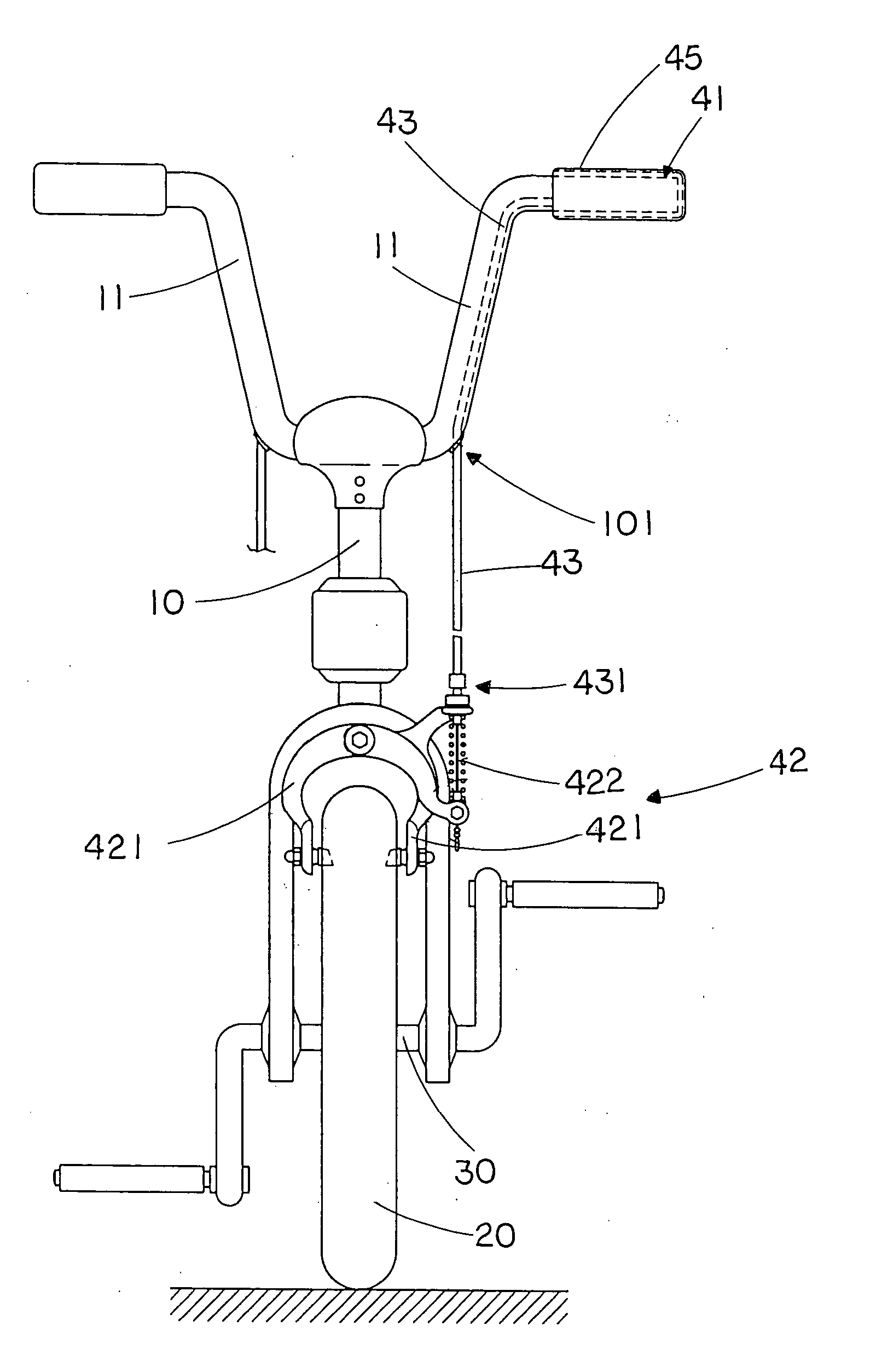
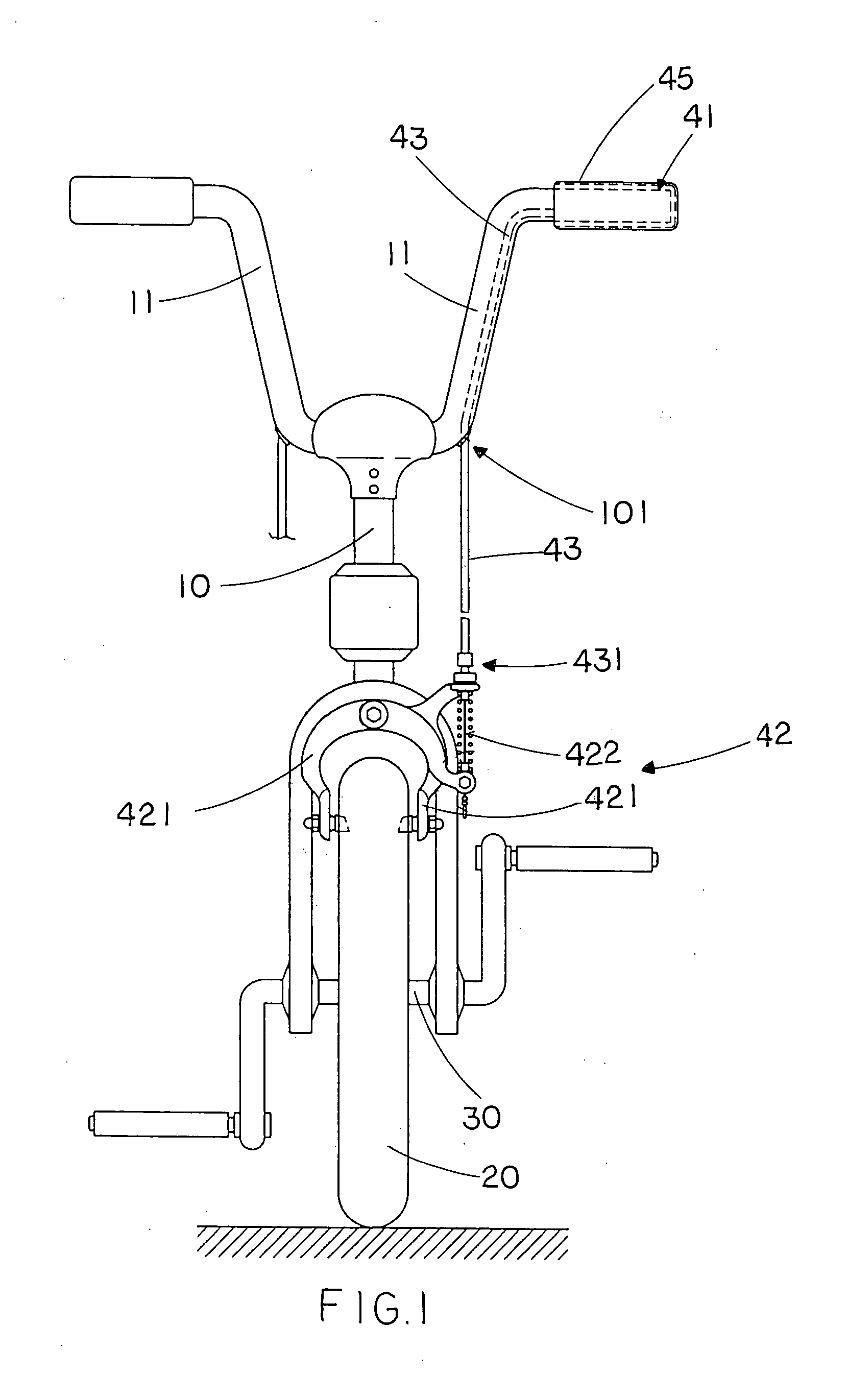
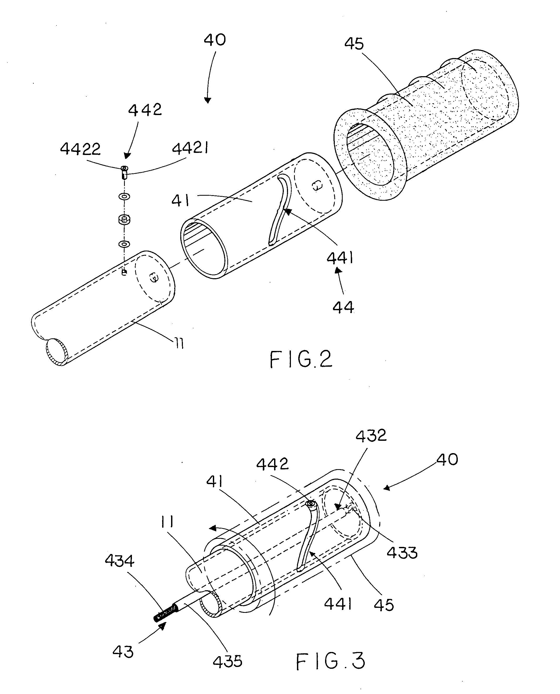
[0029] Referring to FIGS. 1 through 3 of the drawings, a rider propelling vehicle according to a preferred embodiment of the present invention is illustrated, wherein the rider propelling vehicle is embodied as a bicycle as an example while the rider propelling vehicle can be constructed as a stroller or a scooter.

[0030] The rider propelling vehicle comprises a supporting frame 10, having a steering handle 11, for supporting a rider, at least a driving wheel 20 rotatably mounted to the supporting frame 10, a transmission device 30 operatively linked to the driving wheel 20 for transmitting a human power of the rider to a rotational power at the driving wheel 20, and a rotation control brake system 40.

[0031] Accordingly, the bicycle of the rider propelling vehicle comprises two driving wheels 20 wherein the transmission device 30 comprises an endless transmission chain linked between one of the driving wheels 20 and a bicycle pedal of the supporting frame 20 to convert the human po...


PUM


Abstract

A rotation control brake system includes a tubular brake actuator coaxially mounted at a steering handle of a rider propelling vehicle, a brake unit operatively mounted at a position close to a driving wheel of the rider propelling vehicle, and a brake cable having a driving end coupling with the brake unit and an opposed actuating end extended to couple with the brake actuator to retain the brake actuator at a normal driving position. wherein at a braking position, the brake actuator is rotatably, longitudinally and outwardly slid with respect to the steering handle to pull the brake cable that the brake unit is biased against the driving wheel to control a rotational speed of the driving wheel, such that the rider propelling vehicle is adapted for being well controlled while the rider keeps the hand thereof at the steering handle.

Description

BACKGROUND OF THE PRESENT INVENTION [0001] 1. Field of Invention [0002] The present invention relates to a rider propelling vehicle, and more particularly to a rotation control brake system for a rider propelling vehicle such as bicycle or scooter, wherein the rotation control brake system comprises a brake actuator rotatably mounted to a steering handle of the rider propelling vehicle to control the speed thereof through the rotational movement of the brake actuator. [0003] 2. Description of Related Arts [0004] Nowadays, rider propelling vehicles, such as bicycles, strollers, or scooters, are well known and have been considered as a form of transportation, recreation, and exercise. A conventional rider propelling vehicle comprises a supporting frame, having a steering handle, for supporting a rider, at least two wheels spacedly and rotatably mounted to the supporting frame, transmission unit linked to one of the wheels as a driving wheel for transmitting human power to a rotational...

Claims


Application Information

Patent Timeline
Patent Type & Authority Applications(United States)
IPC IPC(8): B62K13/06B62K23/04B62L3/02
CPCB62K23/04Y10T74/2042B62L3/026
Inventor JIUN GU, HONG
Owner GU HONG JIUN
Why Eureka
Try Eureka