Energy saving driving circuit for piezoelectric motor

a driving circuit and piezoelectric technology, applied in piezoelectric/electrostrictive device details, piezoelectric/electrostrictive/magnetostrictive devices, piezoelectric/electrostriction/magnetostriction machines, etc., can solve problems such as energy consumption related to piezoelectric motor driving, and achieve low voltage power supply, good energy efficiency, and low cost

a driving circuit and piezoelectric technology, applied in piezoelectric/electrostrictive device details, piezoelectric/electrostrictive/magnetostrictive devices, piezoelectric/electrostriction/magnetostriction machines, etc., can solve problems such as energy consumption related to piezoelectric motor driving, and achieve low voltage power supply, good energy efficiency, and low cost

US20050285477A1Inactive Publication Date: 2005-12-29WSOU INVESTMENTS LLC

Image

  • Energy saving driving circuit for piezoelectric motor
  • Energy saving driving circuit for piezoelectric motor
  • Energy saving driving circuit for piezoelectric motor

Examples


Embodiment Construction

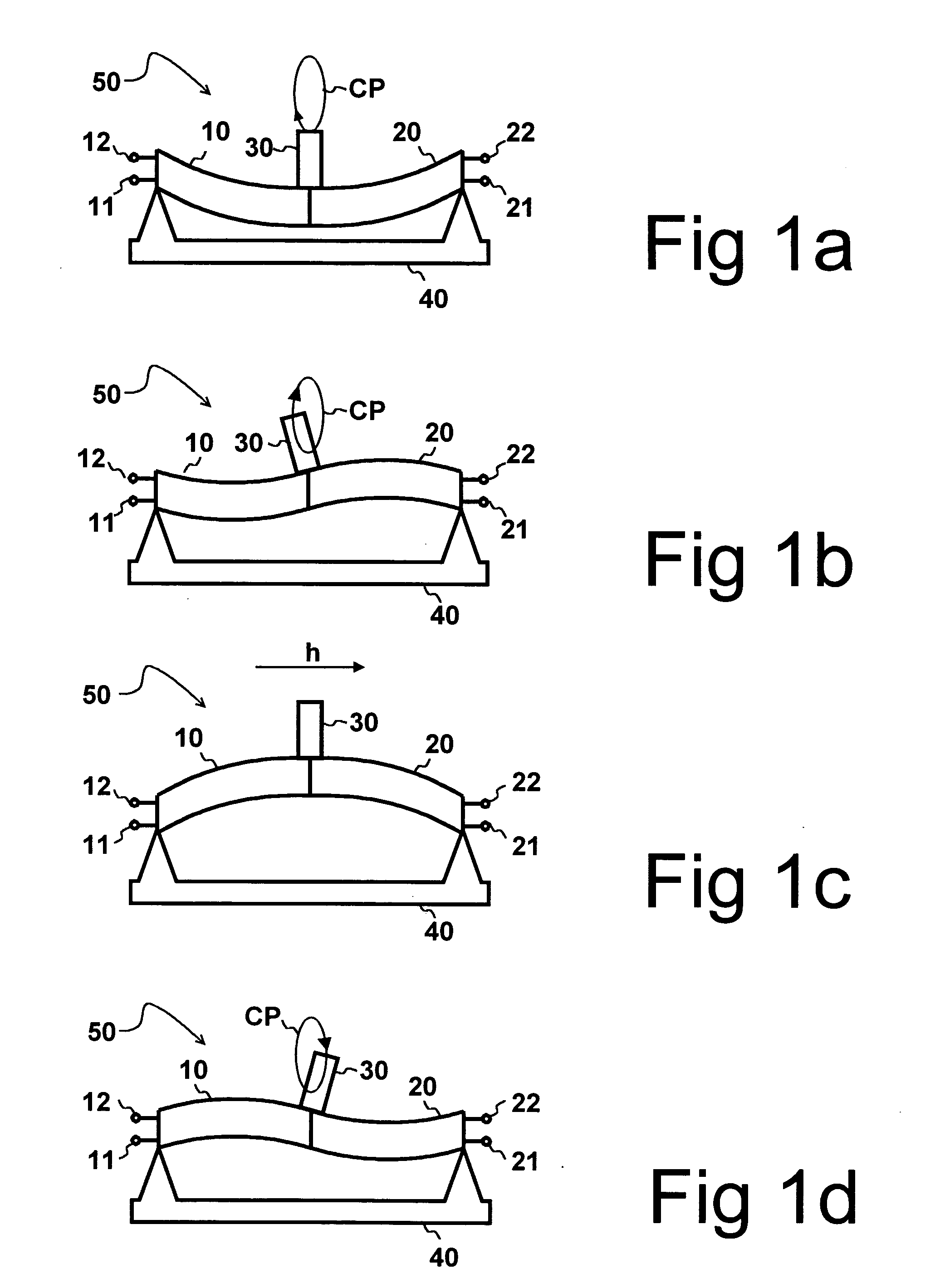
[0029] Referring to FIG. 1a, a piezo-electric actuator 50 may comprise two independently deflectable piezo-elements 10, 20, which have been connected together. A protrusion 30 is attached near the connection point of said two piezo-elements 10, 20. The piezo-elements 10, 20 are supported by a support 40, which allows the deflection of said piezo-elements 10, 20. The degree of deflection of each piezo-element 10, 20 is changed when a voltage is applied between voltage terminals 11,12, 21, 22 of said piezo-elements 10, 20. The piezo-elements 10, 20 may be designed and optimized to be operated using unipolar voltages, i.e. with voltages in the range from zero voltage to a maximum voltage. Preferably, the piezo-electric actuator 50 is implemented using deflectable piezo-elements known as bimorphs by the person skilled in the art.

[0030] The degree of deflection of said two piezo-elements is changed in a cyclic manner when alternating voltages are coupled to the voltage terminals 11, 12,...


PUM


Abstract

In a method and a device according to the present invention, two piezo-elements are driven with two voltages having a phase difference. One of the piezo-elements is charged by an inductive step-up means to a voltage exceeding an available power supply voltage. Subsequently charge, i.e. energy is transferred from the one piezo-element to the other piezo-element by an inductive element. The same inductive element is used in an inductive step-up means and in the transfer of the charge between the two piezo-elements.

Description

CROSS-REFERENCE TO RELATED APPLICATIONS [0001] This application claims priority under 35 USC §119 to Finnish Patent Application No. 20045218 filed on Jun. 11, 2004. FIELD OF THE INVENTION [0002] The present invention relates to a piezo-element driving device and a method for driving piezo-elements, in which two piezo-element driving voltages are provided, said driving voltages being in different phases with respect to each other. The present invention relates also to a mobile device comprising a piezo-element driving device. BACKGROUND OF THE INVENTION [0003] Piezo-electric actuators are used in imaging systems to adjust the positions of zoom and focusing lens systems. Piezo-electric actuators are also used in other systems to move small objects. Driving devices providing suitable driving voltages are required to operate said piezo-electric actuators. Piezo-electric actuators are implemented by using one or more piezo-elements, which are deflected, expanded or contracted when couple...

Claims


Application Information

Patent Timeline
29 Dec 2005
Publication
US20050285477A1
IPC
H01L; H02N; H02N2/06; H02N2/18; H10N30/20; H10N30/80
CPC
H01L41/0906; H02N2/0015; H02N2/067; H02N2/026; H02N2/0075; H02N2/06; H02N2/02; H10N30/202
Inventors
OLLILA, MIKKO