AC magnetic tracking system employing wireless field source

a wireless field source and magnetic tracking technology, applied in the field of ac magnetic tracking systems, can solve the problems of difficult to keep running reliably, significant complexity, and restrict the free movement of subjects, and achieve the effects of low signal level, low power consumption, and detectable eddy current distortion

Inactive Publication Date: 2005-12-29
AIKEN INC D B A POLHEMUS
View PDF17 Cites 16 Cited by
  • Summary
  • Abstract
  • Description
  • Claims
  • Application Information

AI Technical Summary

Benefits of technology

[0013] In existing AC magnetic tracking systems a magnetic field source is held statically and sensors are positioned on a subject or object to be tracked. The difficulties of dealing with these low-level signals on the body, and the necessity of radioing the resulting data back to a base station, make a wireless source according to the invention especially attractive. This invention takes advantage of the fact that the tracking of position and orientation (P&O) between source and sensor is entirely reciprocal; that is, it makes no difference that the source is moving and the sensor is held static.
[0014] According to the invention, a small, lightweight wireless source acts as a “pseudo-sensor” source. Upon activation, the source sends out three continuous low-power magnetic signals, a separate frequency from each of three resonant orthogonal coils, without the need for switching to a receive mode or detecting a synchronizing signal to start the three signals simultaneously. This simple structure allows the source to be kept small and consume little power so that it can operate for over one hour before needing to be re-charged. This design approach thus allows a user

Problems solved by technology

One of the reasons this static source configuration has been used is due to the fact that the drive for the field source typically requires considerable drive current.
These items still considerably constrain free movement of the subject and tend to be uncomfortable to wear not only from being cumbersome but because they cause perspiration from heat and lack of ventilation.
Furthermore, they are difficult to keep running reliably because of the many interconnections involved and the cables being threaded through garments or other items on the subject.
These constraints, plus a requirement to perform calibrations at over 32 position and 32 orientation settings, leads to significant complexity.
Indeed, any attempt to

Method used


Image

  • AC magnetic tracking system employing wireless field source
  • AC magnetic tracking system employing wireless field source
  • AC magnetic tracking system employing wireless field source

Examples


Embodiment Construction

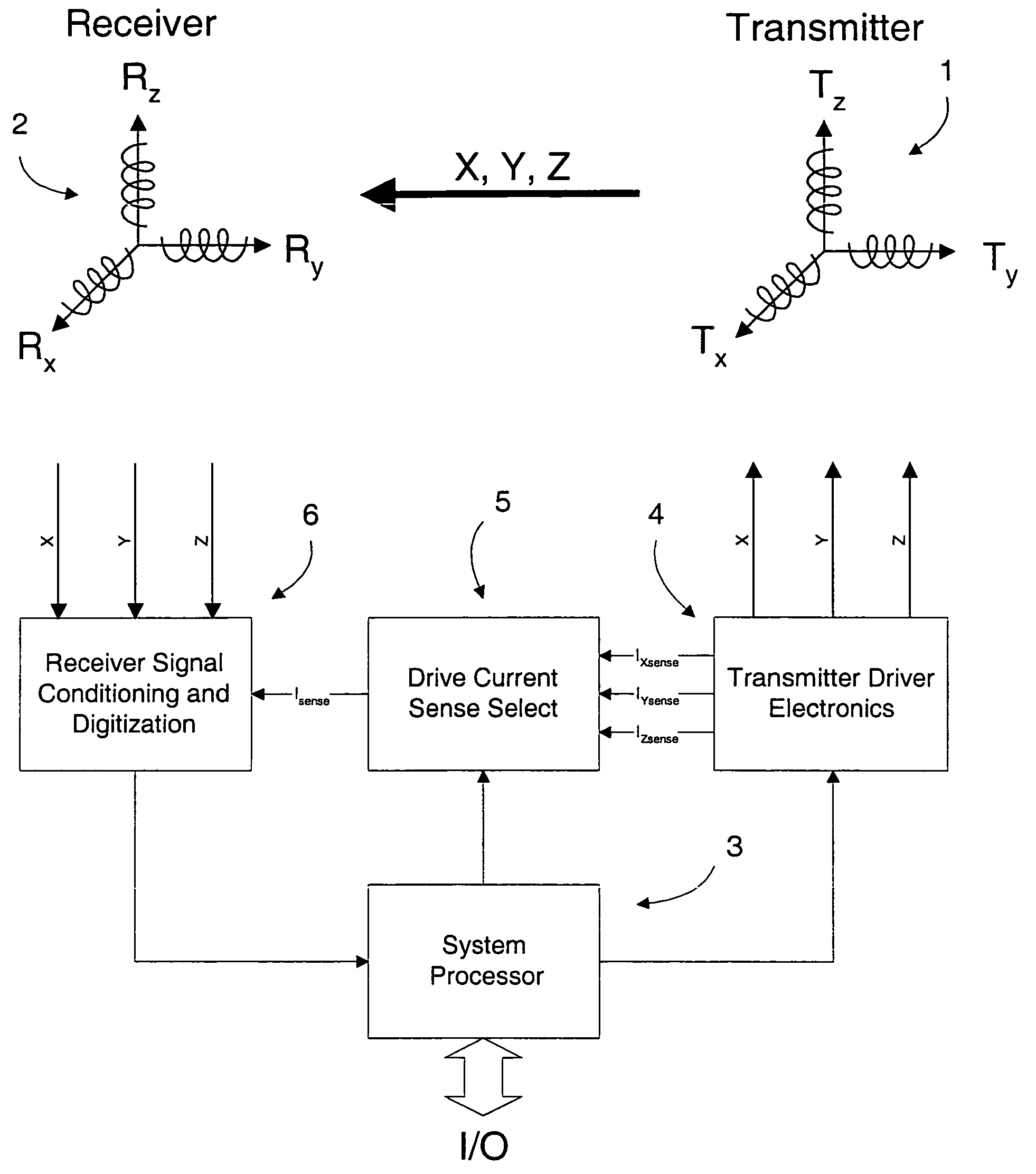
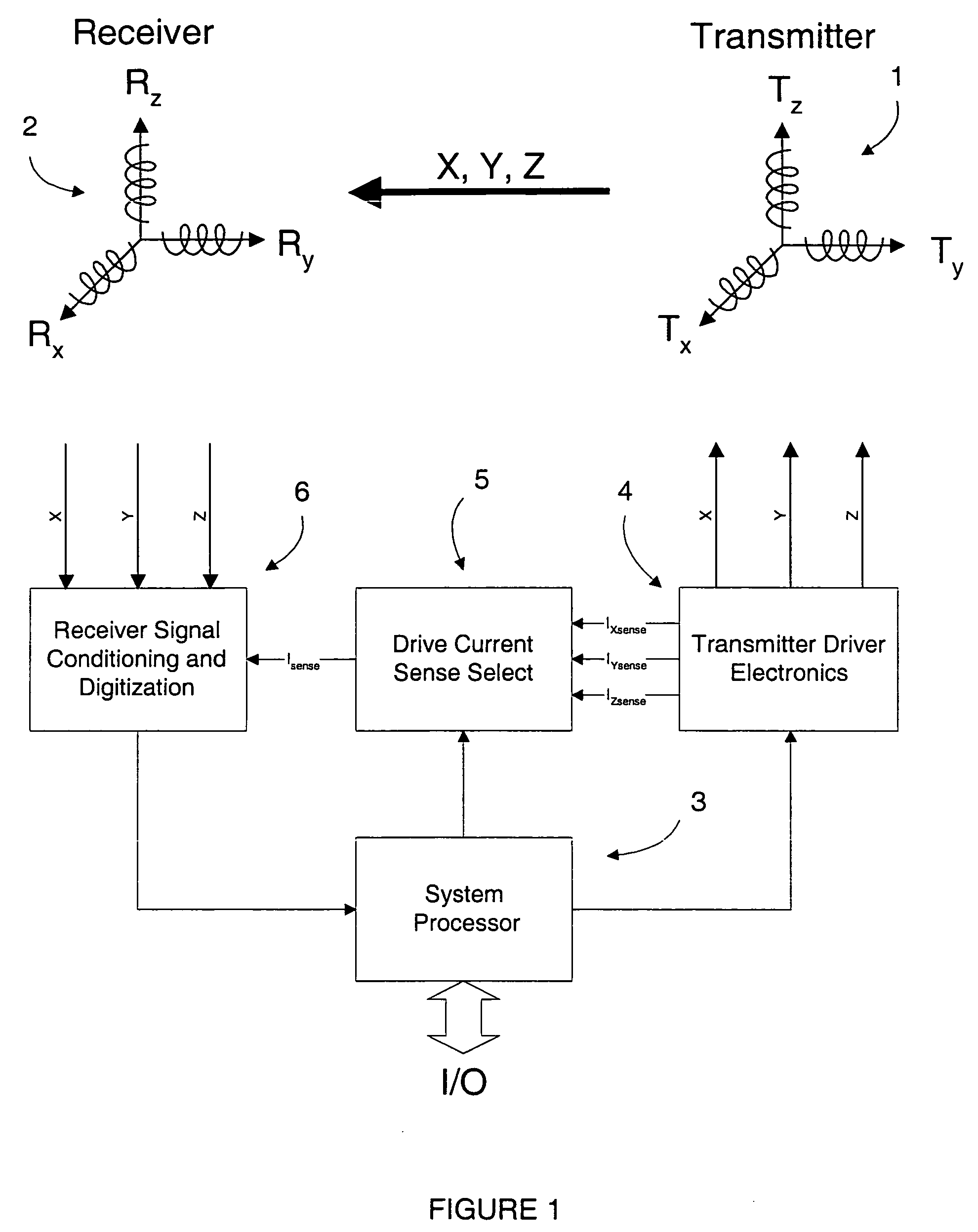
[0021] The expression “frequency set” is used herein to convey the notion that this invention is dependent on creating three independent frequencies, one on each of three coils intended to be arranged geometrically orthogonal to each other, so that the tracker electronics and true sensor intercepting the magnetic field signals can distinguish the proper source axes. For a given system, the frequency sets should be arranged identically from unit-to-unit, and additional frequency sets are chosen so that multiple sources “pseudo-sensors” can navigate in the same environment without repeating frequencies from other pseudo-sensors.

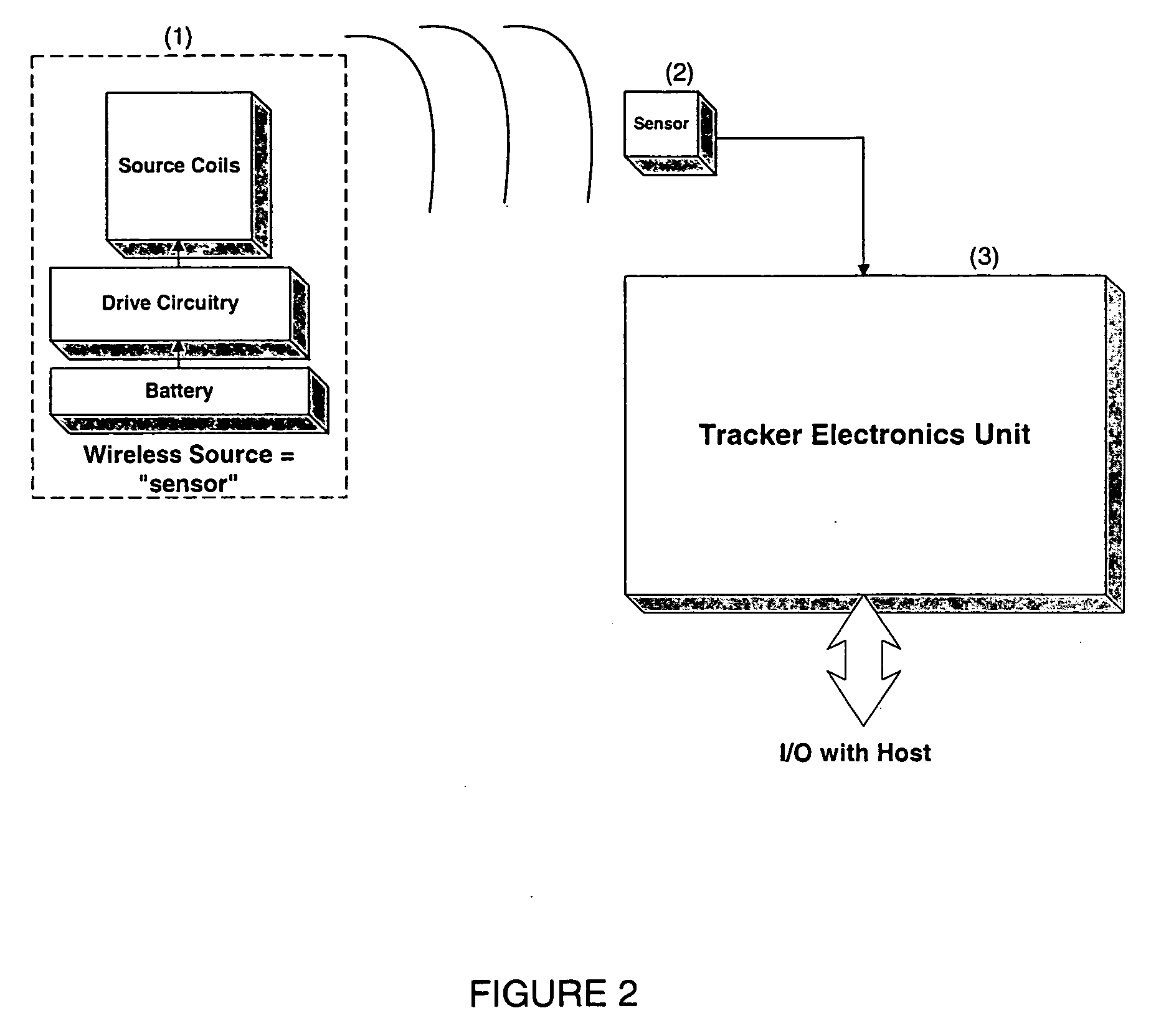
[0022] According to the invention, the tracking of the pseudo-sensor(s) can be accomplished with a single, three-axis set of true sensor coils. The pseudo-sensor source can also be kept quite simple as a self-standing source of the three magnetic fields. As such, the pseudo-sensor source simply creates the signals to be tracked without the need to revert to re...


PUM


Abstract

A small, lightweight field source acts as a “pseudo-sensor” in an AC magnetic tracking system, facilitating wireless operation. Upon activation, the source sends out three continuous low-power magnetic signals, a separate frequency from each of three resonant orthogonal coils, without the need for switching to a receive mode or detecting a synchronizing signal to start the three signals simultaneously. This simple structure allows the source to be kept small and consume little power so that it can operate for over one hour before needing to be re-charged. This design approach thus allows a user or object being tracked to move about freely with no restricting cabling to a base station or even to a body-mounted electronics module and bulky battery. A family of frequencies can be used for each of several such pseudo-sensor sources in order for the base station sensors and electronics to track multiple sources.

Description

REFERENCE TO RELATED APPLICATION [0001] This application claims priority to U.S. Provisional Patent Application Ser. No. 60 / 578,128, filed Jun. 8, 2004, the entire content of which is incorporated herein by reference.FIELD OF THE INVENTION [0002] This invention relates generally to AC magnetic tracking systems and, in particular, to systems of this type which are entirely wireless. BACKGROUND OF THE INVENTION [0003] Position and orientation tracking systems (“trackers”) are well known in the art. For example, U.S. Pat. Nos. 4,287,809 and 4,394,831 to Egli et al.; U.S. Pat. No. 4,737,794 to Jones; U.S. Pat. No. 4,314,251 to Raab; and U.S. Pat. No. 5,453,686 to Anderson, are directed to AC electromagnetic trackers. U.S. Pat. No. 5,645,077 to Foxlin discloses an inertial system, and combination systems, consisting or two different trackers, such as optical and magnetic, are described in U.S. Pat. No. 5,831,260 to Hansen and U.S. Pat. No. 6,288,785 B1 to Frantz et al. Other pertinent re...

Claims


Application Information

Patent Timeline
IPC IPC(8): G01B7/004H01F5/00H01F7/20
CPCH01F7/20G01B7/004
Inventor HIGGINS, ROBERT F.ROUSSEL, MARK N.JONES, HERBERT R. JR.RODGERS, ALLAN G.
Owner AIKEN INC D B A POLHEMUS
Why Eureka
Try Eureka