Impedance matching of an electromagnetic transponder reader

a transponder reader and impedance matching technology, applied in the field of electromagnetic transponders, can solve the problems of inability to meet tuning accuracy constraints, inability to match signals received by demodulators, and inability to match signals, etc., to achieve stable impedance matching

Inactive Publication Date: 2005-12-29
STMICROELECTRONICS SRL
View PDF14 Cites 30 Cited by
  • Summary
  • Abstract
  • Description
  • Claims
  • Application Information

AI Technical Summary

Benefits of technology

[0015] The present invention aims at overcoming the disadvantages of known systems and, in particular, at making the impedance matching stable even in case of a variation in the environmental conditions of terminal operation.

Problems solved by technology

A problem of conventional read / write terminals is that in case of a mismatch of the impedance of the oscillating circuit's antenna, the signal received by the demodulator is disturbed.
Such tolerances are incompatible with the fulfilling of tuning accuracy constraints.
Similarly, such tolerances adversely affect the impedance matching between amplifier 6 and the oscillating circuit.
Further, maintenance problems linked to the impedance matching drift according to environment modifications, for example, after temperature and / or humidity changes, can also be observed.

Method used


Image

  • Impedance matching of an electromagnetic transponder reader
  • Impedance matching of an electromagnetic transponder reader

Examples


first embodiment

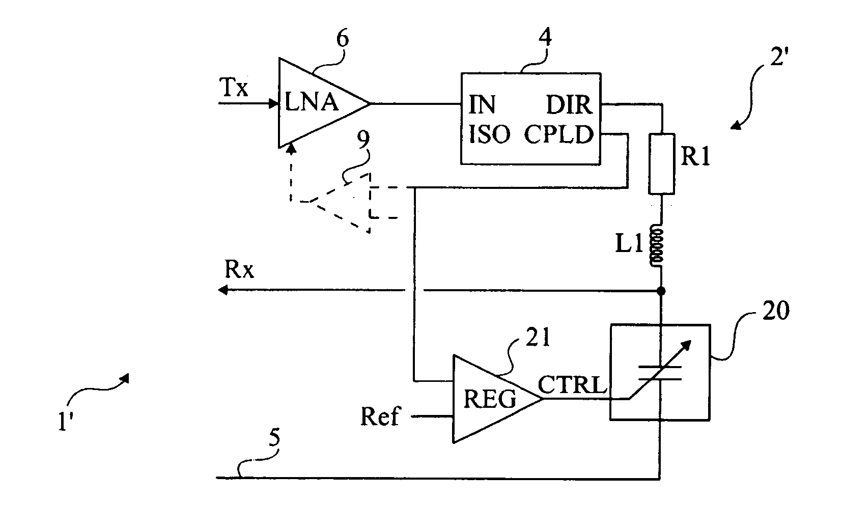
[0028]FIG. 2 partially and schematically shows a read / write terminal 1′ of an electromagnetic transponder (not shown) according to the present invention. Only part of the terminal's components have been shown in FIG. 2, the rest being similar to the structure of a conventional terminal such as illustrated in FIG. 1.

[0029]FIG. 2 shows an amplifier 6 (LNA) for providing an excitation signal to an oscillating circuit 2′ formed of a resistor R1, of an inductance L1, and of a capacitive element 20 in series, and a directional antenna coupler 4 connected between the output of amplifier 6 and oscillating circuit 2′.

[0030] According to the present invention, capacitive element 20 is a variable-capacitance element controllable by a signal CTRL. Signal CTRL is provided by a circuit 21 (REG) having the function of comparing the signal provided by antenna coupler 4 (terminal CPLD) with a reference value REF to control the value of the capacitance of element 20 to maintain the impedance of osci...

second embodiment

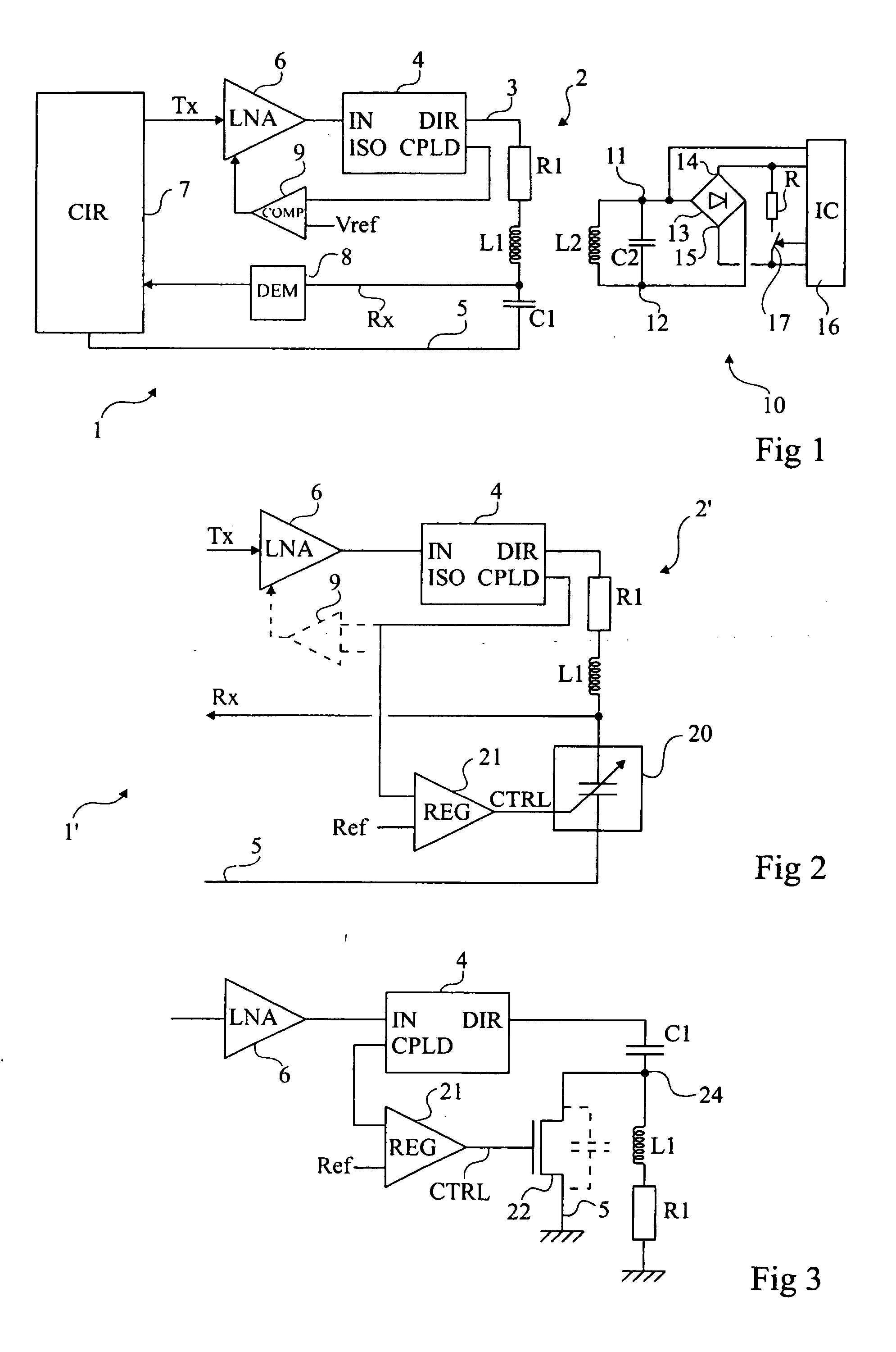
[0034]FIG. 3 shows a control circuit according to the present invention. In this example, circuit 21 providing control signal CTRL controls a MOS transistor 22 assembled in parallel on a series association of inductance L1 with resistor R1. Capacitor C1 being, for example, between this parallel assembly and output DIR of coupler 4 (as an alternative, between this parallel assembly and the ground if this is compatible with the control of switch 22). In this example, the respective positions of capacitor C1 and of inductance L1 have been inverted with respect to FIGS. 1 and 2. This has however no incidence upon the operation.

[0035] Preferably, received signal Rx is sampled from output CPLD of the coupler, which improves the signal-to-noise ratio. Such a connection is also possible in the embodiment of FIG. 2. The only precaution is for the time constant of the regulation loop to be much greater (at least ten times) than the back-modulation period to avoid loosing the back-modulation i...


PUM


Abstract

A terminal for generating an electromagnetic field, including an oscillating circuit capable of receiving a high-frequency A.C. excitation voltage via an amplifier and a directional coupler, the oscillating circuit having at least one element of variable capacitance, and circuitry for modifying the value of this capacitance according to the amplitude of a signal extracted from the coupler.

Description

BACKGROUND OF THE INVENTION [0001] 1. Field of the Invention [0002] The present invention relates to systems using electromagnetic transponders, that is, transceivers (generally mobile) likely to be interrogated, contactless and wireless, by a unit (generally fixed), called a read and / or write terminal. The present invention more specifically relates to read / write terminals of transponders with no autonomous power supply, which extract the power supply required by the electronic circuits included therein from a high-frequency field radiated by an antenna of the terminal. [0003] 2. Discussion of the Related Art [0004]FIG. 1 very schematically shows in the form of blocks an electromagnetic transponder read terminal 1 and a transponder 10 intended to communicate with such a terminal. [0005] On the read terminal side, a series oscillating circuit 2 formed of an inductance L1, forming an antenna, in series with a capacitor C1 (and generally a resistor R1), between an output terminal 3 of...

Claims


Application Information

Patent Timeline
Patent Type & Authority Applications(United States)
IPC IPC(8): G01S13/75G06K7/00G06K19/07
CPCG06K7/0008G01S13/758
Inventor ENGUENT, JEAN-PIERRE
Owner STMICROELECTRONICS SRL
Why Eureka
Try Eureka