Tactile display device and touch panel apparatus with tactile display function

Inactive Publication Date: 2005-12-29
PIONEER CORP
View PDF10 Cites 173 Cited by
  • Summary
  • Abstract
  • Description
  • Claims
  • Application Information

AI Technical Summary

Benefits of technology

[0044] According to this aspect, the viscosity change of the electrorheological fluid layer is presented as a change in or of the visual information such as the display pattern displayed on the display device. Such a change means a change in or of the display pattern, and/or a change in or of the intensity of the display light, for example. Realizing the viscosity change by changing the visual information simplifies the construction or structure of the touch panel apparatus, which is further efficient.
[0045] As described above, in the tactile display device of the invention, since there are

Problems solved by technology

Specifically, an effort to control the viscosity of the electrorheological fluid by controlling the applied voltage for each pixel composing a cert

Method used


Image

  • Tactile display device and touch panel apparatus with tactile display function
  • Tactile display device and touch panel apparatus with tactile display function
  • Tactile display device and touch panel apparatus with tactile display function

Examples


first embodiment

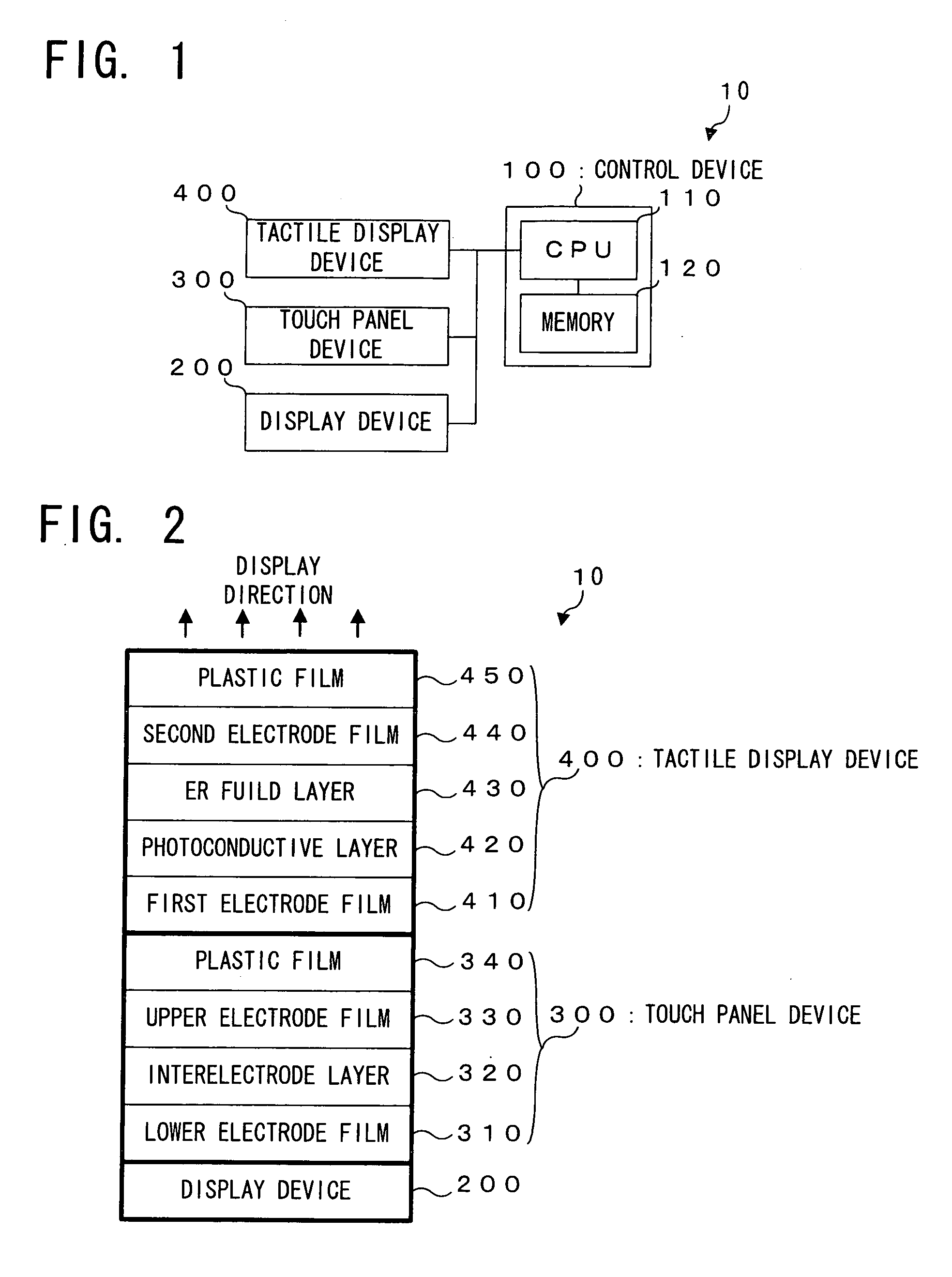
[0056] (Structure of Touch Panel Apparatus 10) First of all, an explanation will be made on a structure of the touch panel apparatus with tactile display function according to the first embodiment of the invention (hereinafter referred to as a “touch panel apparatus 10” as appropriate), with reference to FIG. 1. FIG. 1 shows the touch panel apparatus 10 in a block diagram.

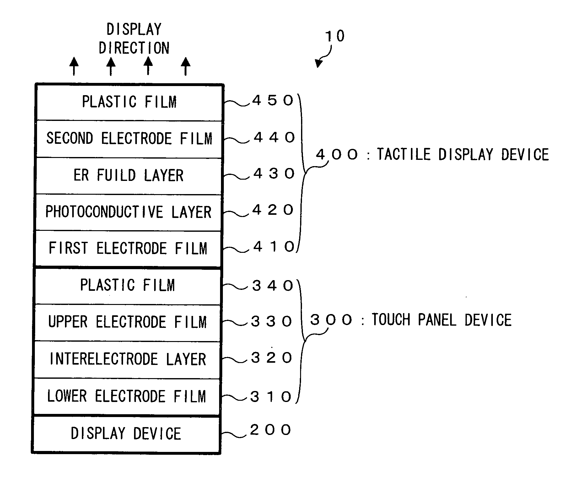
[0057] In FIG. 1, the touch panel apparatus 10 is provided with: a control device 100; a display device 200; a touch panel device 300; and a tactile display device 400. The touch panel apparatus 10 is an example of the touch panel apparatus with tactile display function according to the present invention, which is constructed in such a manner that information can be inputted via the touch panel device 300, with the tactile information inputted via the tactile display device 400, on the basis of various key images, such as numerics or characters, visually displayed on the display device 200.

[0058] The control devi...

second embodiment

[0096] In the aforementioned first embodiment, there is even a possibility of a discomfort feeling about the operation, if the viscosity of the electrorheological fluid layer 430 does not change even in the case that the operator depresses the plastic film 450 to select the visual information such as a button. In the second embodiment, this problem is solved by the CPU 110 which performs a tactile addition process as explained below (i.e. acts as an example of the “change addition device” according to the present invention). Hereinbelow, an explanation will be made on the second embodiment of the present invention, with reference to FIG. 6 and FIG. 7. FIG. 6 schematically illustrates a display screen in the tactile addition process in a plan view, and FIG. 7 is a flow chart of the tactile addition process.

[0097] Incidentally, a construction or structure in the second embodiment is the same as the first embodiment, because the second embodiment is of an explanation about the process...

modified embodiment

[0108] Incidentally, the construction or structure of the touch panel apparatus with tactile display function is not limited to the construction or structure illustrated in the aforementioned embodiments. For example, it is easy to employ a construction or structure as mentioned below. Now, an explanation will be made on a modified embodiment of the present invention, with reference to FIG. 8. FIG. 8 schematically illustrates a structure of a tactile display device 500 of a touch panel apparatus with tactile display function 20 in the modified embodiment of the present invention. Incidentally, in this figure, elements or components the same as in FIG. 2 carry the same numerals, and the explanation of them is omitted.

[0109] In FIG. 8, the touch panel apparatus with tactile display function 20 is different from the aforementioned embodiments, in a point that there is provided with the tactile display device 500, instead of the tactile display device 400, in which an elastic layer 510...


PUM


Abstract

Conductivity of a photoconductive layer 420 changes in accordance with a display pattern made of black and white, which is displayed on a display device 200 of a touch panel apparatus with tactile display function 10. With this change of the conductivity, viscosity of an electrorheological fluid layer 430 changes in accordance with this display pattern. This change of the viscosity is presented to an operator, as tactile information corresponding to the display pattern displayed as the visual information.

Description

BACKGROUND OF THE INVENTION [0001] 1. Field of the Invention [0002] The present invention relates to a tactile display device for displaying tactile information and further relates to a touch panel apparatus with such a tactile display device. [0003] 2. Description of the Related Art [0004] As such a tactile display method, there is presented a method of controlling an appearance of a convex key by means of an electrorheological fluid (ER fluid), for example (Japanese Patent Application Laid-Open No. Hei 11-273501). [0005] In this method, the electrorheological fluid is sealed within a plate-like receptacle or box disposed above a display device. Then, an electrical power distribution over this fluid is controlled in such a manner that a part or area of the electrorheological fluid (i.e. the fluid which viscosity is changed by electricity) corresponding to the convex key is relieved or embossed by means of a pump as a pressure device. As a result, an embossed key can be appeared. [0...

Claims


Application Information

Patent Timeline
IPC IPC(8): G09G5/00
CPCG06F2203/04809G06F3/04886G09B21/004
Inventor FUNAKI, JUN
Owner PIONEER CORP
Why Eureka
Try Eureka