Image drawing apparatus and image drawing method

a technology of image drawing and drawing method, applied in the direction of electrical apparatus, printing, pictoral communication, etc., to achieve the effect of reducing density and resolution unevenness

Inactive Publication Date: 2005-12-29
FUJIFILM HLDG CORP +1
View PDF5 Cites 34 Cited by
  • Summary
  • Abstract
  • Description
  • Claims
  • Application Information

AI Technical Summary

Benefits of technology

[0013] The present invention has been conceived based on consideration of the above circumstances. An object of the present invention is therefore to provide an image drawing apparatus and an image drawing method for multiple-overlay image drawing that can reduce unevenness in density and resolution caused by an error in an installation angle of an image drawing head and by a pattern distortion.

Problems solved by technology

Furthermore, a pixel pitch along the direction perpendicular to the scanning direction does not strictly match a pixel pitch of other parts due to an error in an installation angle or in pixel positions in a tiny area that is smaller than resolution and corresponds to each area between the columns of the active pixels.

Method used


Image

  • Image drawing apparatus and image drawing method
  • Image drawing apparatus and image drawing method
  • Image drawing apparatus and image drawing method

Examples


Embodiment Construction

[0060] Hereinafter, an exposure apparatus as an embodiment of an image drawing apparatus of the present invention will be described in detail with reference to the accompanying drawings.

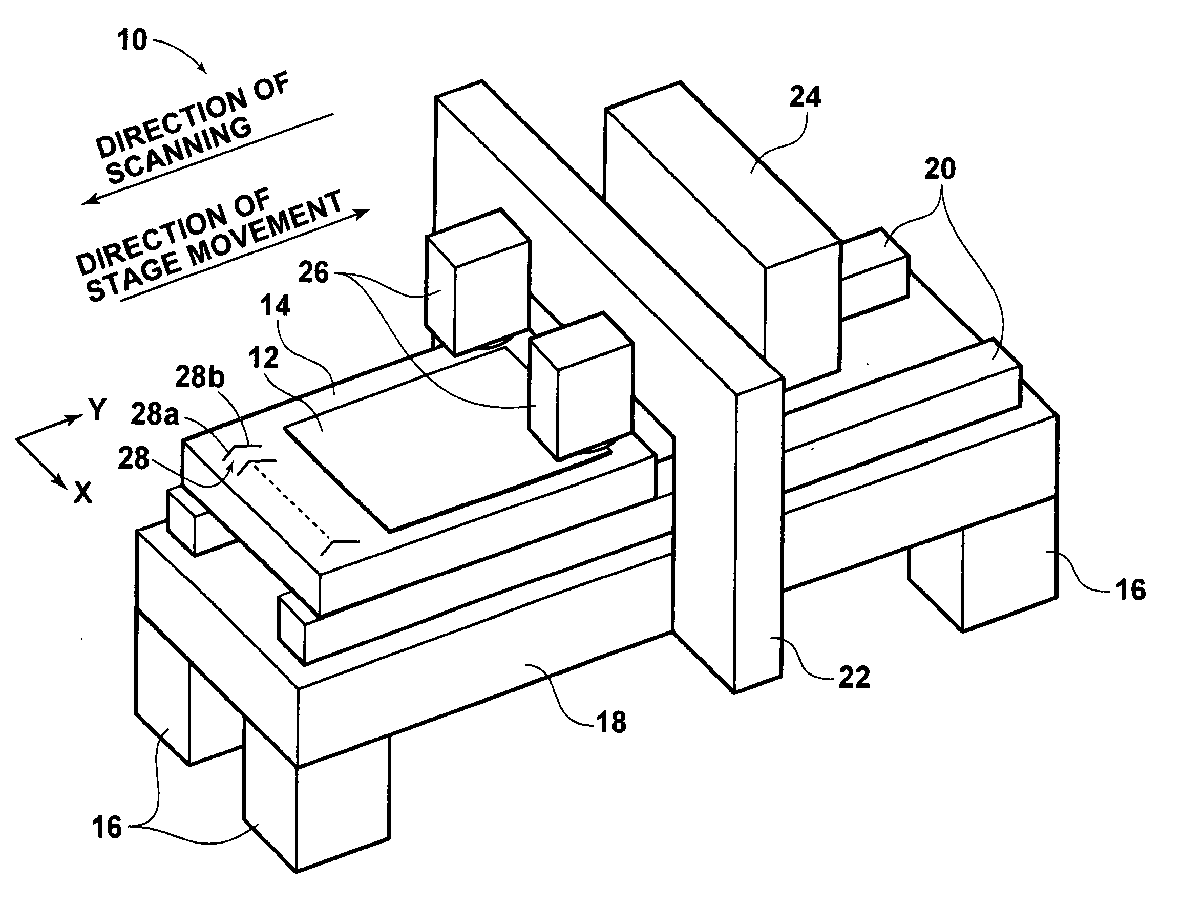
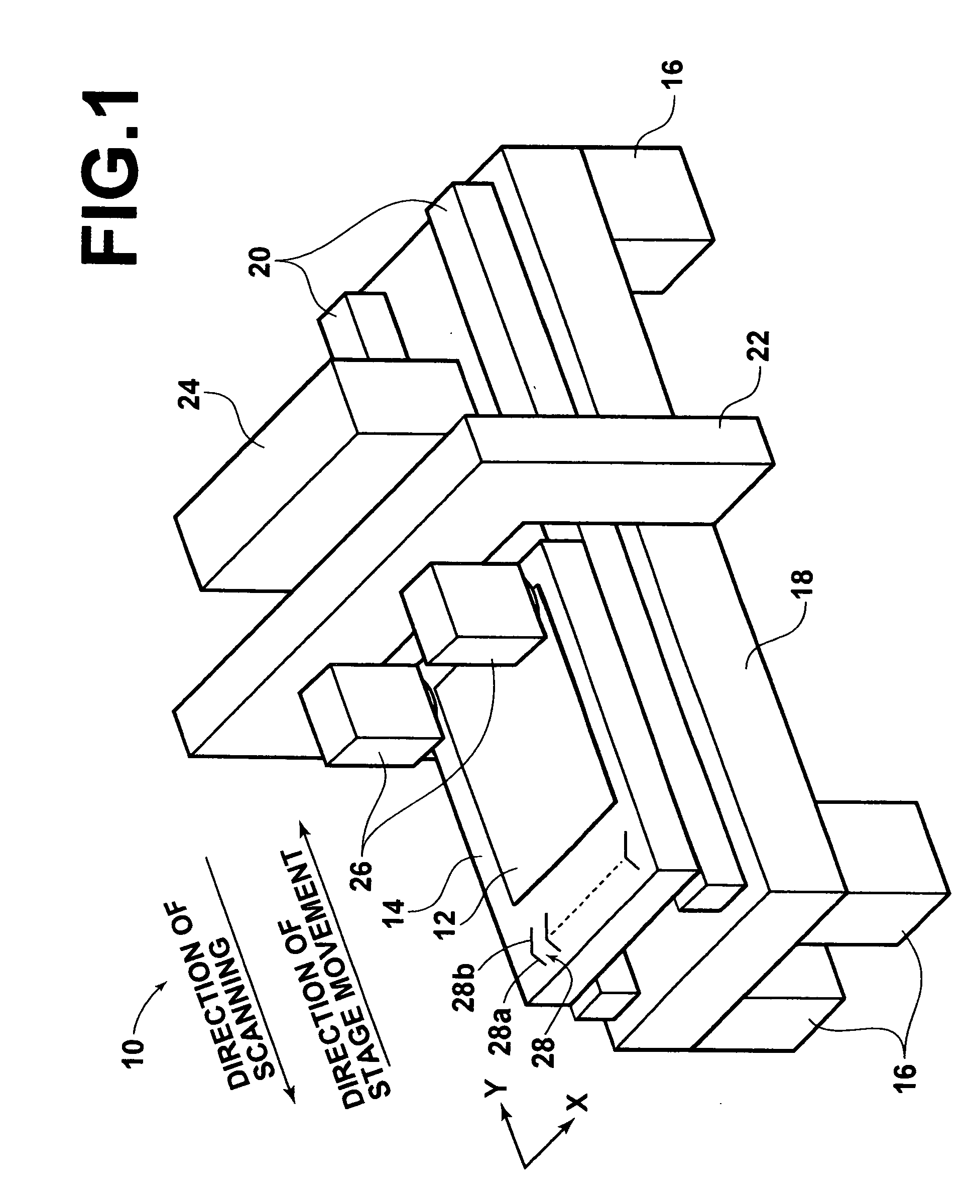
[0061] As shown in FIG. 1, an exposure apparatus 10 of this embodiment comprises a planar stage 14 for holding a sheet 12 of photosensitive material (hereinafter referred to as the photosensitive sheet 12) by suction. On the upper surface of a thick plate-like mount 18 supported by four legs 16 are placed two guide rails 20 elongated along the direction of movement of the stage 14. The stage 14 is placed in such a manner that the direction of longer sides thereof is parallel to the direction of movement thereof. The stage 14 is supported by the guide rails 20 so that the stage 14 can move back and forth along the rails. The exposure apparatus 10 also comprises a stage driving unit (not shown) for driving the stage 14 along the guide rails 20.

[0062] A U-shaped gate 22 is situated at the center of th...


PUM


Abstract

In an image drawing apparatus and an image drawing method for multiple-overlay image drawing, uneven density and resolution caused by an error of installation angle of an image drawing head and by pattern distortion can be reduced. A rectangular two-dimensional pixel array is installed in each of exposure heads in an exposure apparatus (image drawing apparatus) so as to make a predetermined angle with the scanning direction, facing an exposure surface. Slits and photo detectors detect in the exposure surface an actual installation angle of a representative light-spot column near the center of the pixel array. Active pixels in the pixel array are selected so as to realize multiple-overlay exposure ideally by causing overexposure and underexposure to be minimal in an area near the representative light-spot column, based on the measured angle. Exposure is carried out by causing only the active pixels to operate.

Description

BACKGROUND OF THE INVENTION [0001] 1. Field of the Invention [0002] The present invention relates to an image drawing apparatus and an image drawing method. More specifically, the present invention relates to an image drawing apparatus and an image drawing method for forming a two-dimensional pattern represented by image data on an image drawing surface by multiple-overlay image drawing. [0003] 2. Description of the Related Art [0004] There are known various kinds of image drawing apparatuses, each comprising an image drawing head for forming a desired two-dimensional pattern represented by image data on an image drawing surface. As a representative example of such an image drawing apparatus, an exposure apparatus for forming a desired two-dimensional pattern on an exposure surface of a photosensitive material or the like by using an exposure head in order to generate a semi-conductor substrate or printing plate can be listed. Such an exposure head in an exposure apparatus generally...

Claims


Application Information

Patent Timeline
Patent Type & Authority Applications(United States)
IPC IPC(8): B41J2/465H04N1/04H04N1/10H04N1/19H04N1/193H04N1/195
CPCB41J2/465H04N1/00734H04N1/00745H04N1/1008H04N1/19H04N2201/0436H04N1/193H04N1/1933H04N1/195H04N1/19573H04N1/1906G03F7/20
Inventor SUMI, KATSUTOKOWADA, KAZUTERUSUZUKI, ISSEI
Owner FUJIFILM HLDG CORP
Why Eureka
Try Eureka