Three-group zoom lens
a three-group, zoom lens technology, applied in the field of zoom lenses, can solve the problems of difficult shortening the length of the zoom lens, affecting the quality of the image, and the total length of the optical system cannot be shortened, so as to achieve the effect of high resolution capability and picture quality, and favorable correction of various aberrations
- Summary
- Abstract
- Description
- Claims
- Application Information
AI Technical Summary
Benefits of technology
Problems solved by technology
Method used
Image

Examples
embodiment 1
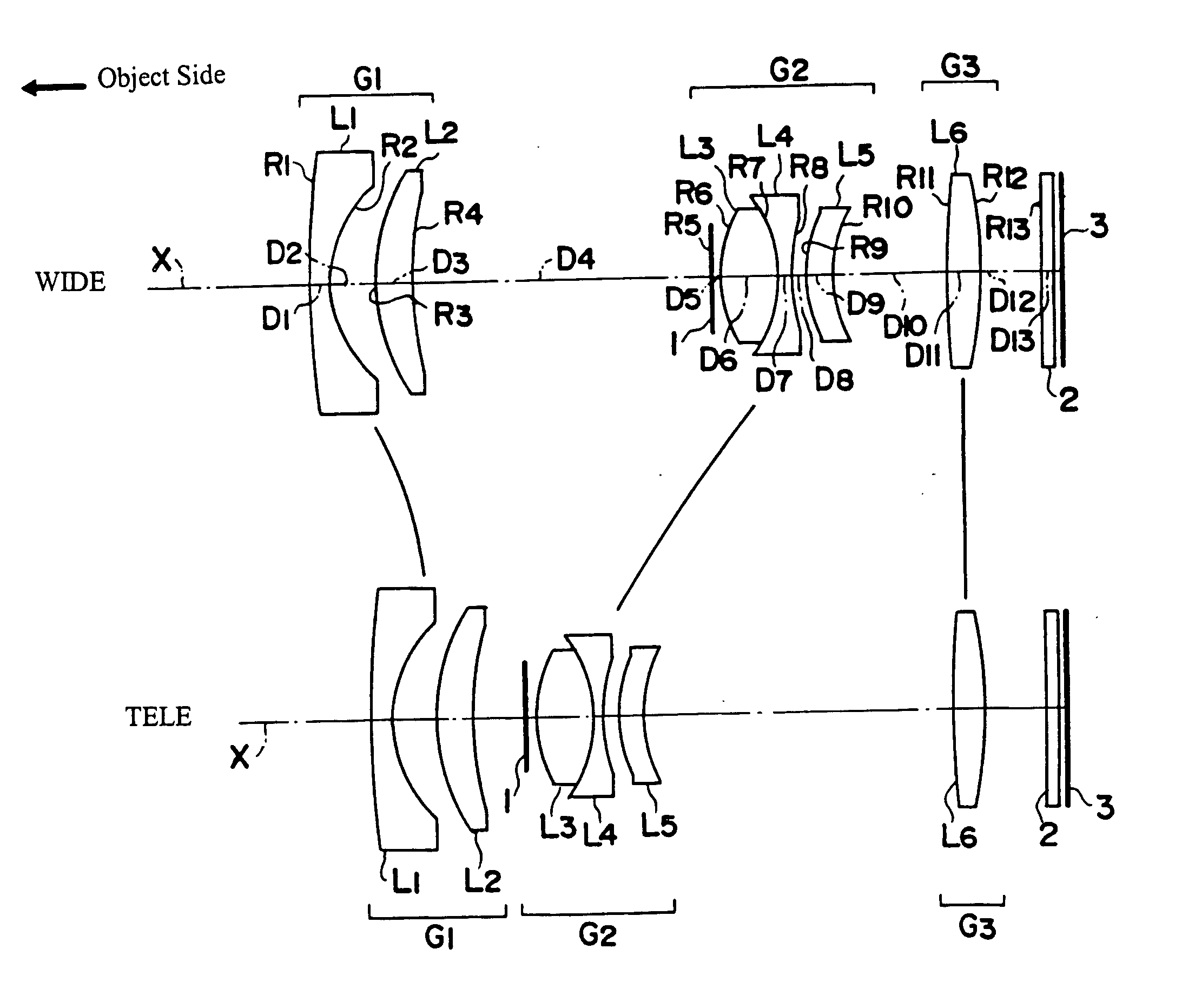
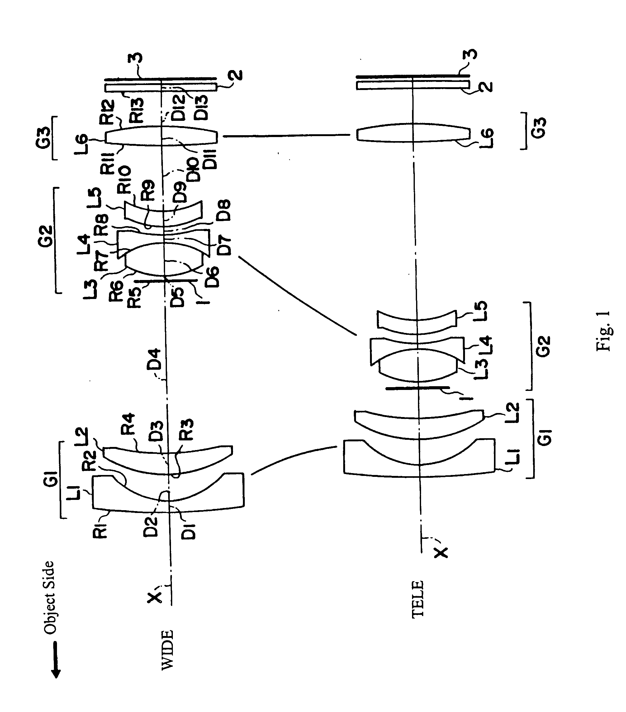
[0054]FIG. 1 shows a cross-sectional view of the three-group zoom lens of Embodiment 1 of the present invention. Table 1 below lists the surface number # in order from the object side, the radius of curvature R (in mm) of each surface on the optical axis, the on-axis surface spacing D (in mm), as well as the refractive index Nd and the Abbe number Vd (both at the d-line of 587.6 nm) of each optical element for Embodiment 1. Listed in the bottom portion of Table 1 are the focal length f (in mm) and the f-number FNO at the wide-angle end and at the telephoto end, and the maximum field angle 2ω at the wide-angle end and at the telephoto end for Embodiment 1.
TABLE 1#RDNdvd 1*167.09971.101.8034840.4 2*5.94212.5139.64622.071.9228620.9417.7149D4 (variable)5∞0.5066.13403.401.7440044.87−6.13400.561.7282528.589.07530.88 9*6.20721.431.5084256.410*8.1134D10 (variable)11 45.81651.821.5084256.412 −24.58623.7613 ∞0.851.5168064.2f = 6.25 − 17.25FNO = 2.9 − 4.92ω = 62.4°− 23.8°
[0055] The lens surf...
embodiment 2
[0061] Embodiment 2 is very similar to Embodiment 1 and therefore is well shown by FIG. 1. Embodiment 2 differs from Embodiment 1 in its lens element configuration by having different radii of curvature of the lens surfaces, different aspheric coefficients of the aspheric lens surfaces, some different optical element surface spacings, and some different refractive indexes and Abbe numbers.
[0062] Table 5 below lists the surface number # in order from the object side, the radius of curvature R (in mm) of each surface on the optical axis, the on-axis surface spacing D (in mm), as well as the refractive index Nd and the Abbe number vd (both at the d-line of 587.6 nm) of each optical element for Embodiment 2. Listed in the bottom portion of Table 5 are the focal length f (in mm) and the f-number FNO at the wide-angle and telephoto ends, and the maximum field angle 2ω at the wide-angle end and at the telephoto end for Embodiment 2.
TABLE 5#RDNdvd 1*93.07331.101.8034840.4 2*5.95712.5439....
embodiment 3
[0069] Embodiment 3 is very similar to Embodiment 1 and therefore is well shown by FIG. 1. Embodiment 3 differs from Embodiment 1 in its lens element configuration by having different radii of curvature of the lens surfaces, different aspheric coefficients of the aspheric lens surfaces, some different optical element surface spacings, and some different refractive indexes and Abbe numbers.
[0070] Table 9 below lists the surface number # in order from the object side, the radius of curvature R (in mm) of each surface on the optical axis, the on-axis surface spacing D (in mm), as well as the refractive index Nd and the Abbe number vd (both at the d-line of 587.6 nm) of each optical element for Embodiment 3. Listed in the bottom portion of Table 9 are the focal length f (in mm) and the f-number FNO at the wide-angle and telephoto ends, and the maximum field angle 2ω at the wide-angle end and the telephoto end for Embodiment 3.
TABLE 9#RDNdvd 1*189.32261.101.8034840.4 2*6.15552.4938.94...
PUM
 Abstract
Description
Claims
Application Information
 - R&D
- Intellectual Property
- Life Sciences
- Materials
- Tech Scout
- Unparalleled Data Quality
- Higher Quality Content
- 60% Fewer Hallucinations
Browse by: Latest US Patents, China's latest patents, Technical Efficacy Thesaurus, Application Domain, Technology Topic, Popular Technical Reports.
© 2025 PatSnap. All rights reserved.Legal|Privacy policy|Modern Slavery Act Transparency Statement|Sitemap|About US| Contact US: help@patsnap.com