Blade driving apparatus for cameras

a technology of driving apparatus and blades, which is applied in the direction of television systems, instruments, printing, etc., can solve the problems of low cost, achieve the effects of reducing manufacturing costs, facilitating assembly work, and reducing the dimension in the direction of the optical axis

Active Publication Date: 2005-12-29
COPAL CO LTD
View PDF5 Cites 26 Cited by
  • Summary
  • Abstract
  • Description
  • Claims
  • Application Information

AI Technical Summary

Benefits of technology

[0021] In the blade driving apparatus for cameras in which each of the shutter device, the stop device, and the filter device, driven by the electromagnetic driving source such as the motor, is constructed as an independent unit, or at least two of these devices are constructed as one unit, the present invention is designed so that all components are mounted to one surface of the base plate, and thus has the advantages of facilitating the assembly work and of reducing the manufacturing cost. Moreover, since all components are assembled in turn with respect to one surface of the base plate, a first assembled component is pressed against the base plate side by a subsequently assembled component. Whereby, the whole number of fixing members (means) can be made smaller than in a conventional structure, and this offers a cost advantage. In case adopting the type described in each of Kokai Nos. 2003-186079 and 2004-32873 as the electromagnetic driving source, there is the advantage that the dimension in the direction of the optical axis is further reduced so that the slim design of the entire apparatus is attained.

Problems solved by technology

When the blade driving apparatus for cameras is also constructed so that the yoke is held, together with the coil, between the base plate and the cover plate or between the base plate and the partition plate, the mounting member of a stator becomes unnecessary, resulting in low cost.

Method used


Image

  • Blade driving apparatus for cameras
  • Blade driving apparatus for cameras
  • Blade driving apparatus for cameras

Examples


embodiment 1

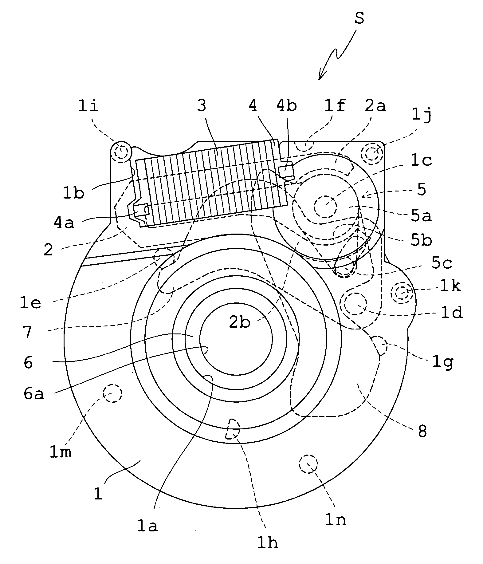
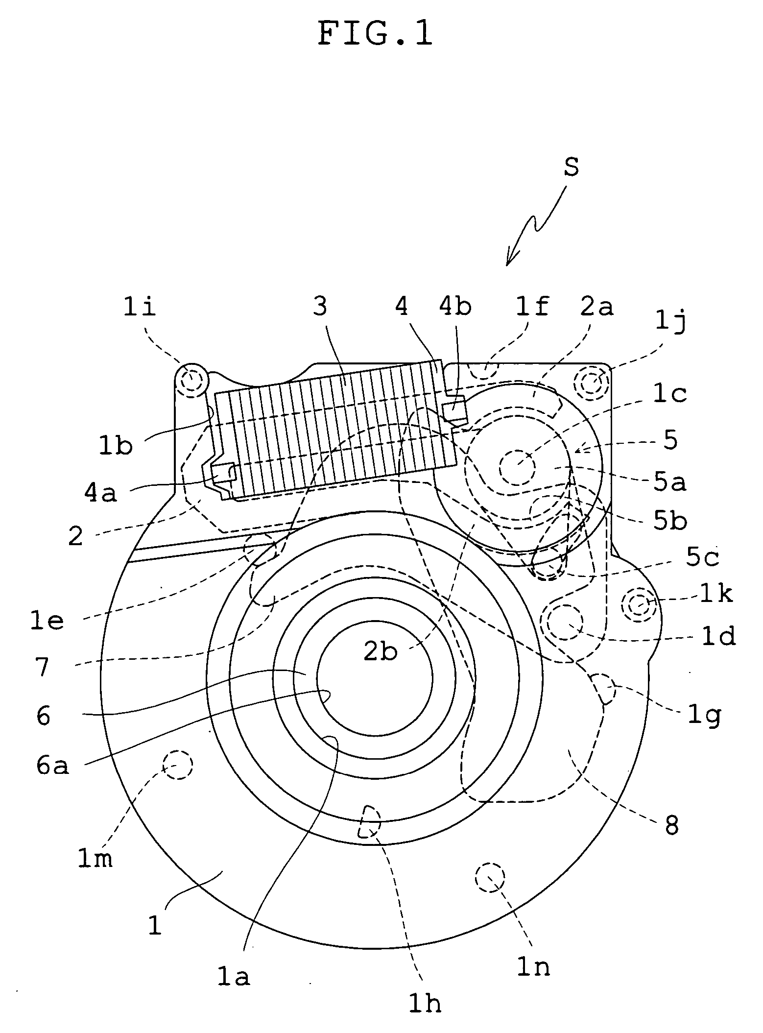
[0036] The structure of this embodiment will be first described. FIG. 1 shows the shutter device S of the embodiment, viewed from the object side. In a state where the shutter device is set to the camera, therefore, a solid-state image sensor is placed on the back side of FIG. 1. A base plate 1, made of synthetic resin, is constructed of a relatively thick member because all components to be described later are mounted to the base plate. The base plate 1 has a circular aperture section 1a for a photographing optical path at about the middle and a notch 1b on a part of the periphery. The object side of the aperture section 1a is configured into a concavity such that a diameter increases gradually and at least one part of a photographic lens is placed in the concavity so that the slim design of the camera is achieved. The surface on the solid-state image sensor side of the base plate 1 is provided with a step shank 1c consisting of a thick shank portion on the base plate side and a fi...

embodiment 2

[0053] In accordance with FIGS. 6-9, Embodiment 2 will be explained. In this embodiment, the shutter device and the stop device are constructed as one unit. The structure of the shutter device is substantially same as in Embodiment 1. Thus, in Embodiment 2, the same numerals and symbols as in Embodiment 1 are used for members and parts described in Embodiment 1 and the explanation of these members is omitted. However, Embodiment 2 is equipped with the stop device, in addition to the shutter device. Hence, the base plate 1, the partition plate 6, and the cover plate 9 in Embodiment 2 are larger than in Embodiment 1 and their shapes are partially changed. As such, in Embodiment 2, reference is made to respects that these plate members are different from those of Embodiment 1 and to explain the structure inherent to Embodiment 2.

[0054] Since Embodiment 2 is equipped with the stop device, an intermediate plate 10 (see FIG. 7) is interposed between the partition plate 6 and the cover pl...


PUM


Abstract

A blade driving apparatus for cameras includes a base plate having an aperture for a photographing optical path; a cover plate having the aperture for the photographing optical path, provided with a blade chamber between the base plate and the cover plate; at least one blade rotatably mounted to the base plate in the blade chamber; and at least one electromagnetic driving source driving the blade. The electromagnetic driving source includes a rotor magnetized to have a plurality of magnetic poles at preset angles on its peripheral surface and having a driving pin for driving pin for driving the blade by its rotation, a yoke having a plurality of magnetic pole sections opposite to the peripheral surface of the rotor, and a coil wound through the yoke. At least, the rotor and the yoke are interposed between the base plate and the cover plate so that, at least, the rotor is rotatably mounted to the base plate.

Description

BACKGROUND OF THE INVENTION [0001] 1. Field of the Invention [0002] This invention relates to a blade driving apparatus for cameras in which each of a shutter device, a stop device, and a filter device is constructed as an independent unit, or at least two of them are constructed as one unit. [0003] 2. Description of Related Art [0004] A lens shutter device (hereinafter referred to as a shutter device), a stop device, and a filter device, in recent years, incorporated in a camera have blade members so that they are reciprocated by an electromagnetic driving source (an actuator such as a motor or a plunger). Such shutter devices are often designed so that two shutter blades are rotated in opposite directions. However, some of the shutter devices incorporated in cameras of extremely small lens diameters, including cameras for mobile phones, are constructed with a single shutter blade. [0005] Recently, stop devices incorporated in cameras of relatively small lens diameters have come to...

Claims


Application Information

Patent Timeline
Patent Type & Authority Applications(United States)
IPC IPC(8): G03B9/08G03B9/10G03B29/00
CPCG03B9/10H04M2250/52G03B29/00
Inventor KIHARA, TOMOKAZU
Owner COPAL CO LTD
Why Eureka
Try Eureka