Secondary battery, cap assembly thereof and method of mounting safety valve therefor

a secondary battery and safety valve technology, applied in the field of secondary batteries, can solve the problems of battery explosion and burn, inability to meet the performance, and difficulty in manufacturing conventional structures, and achieve the effects of improving the safety valve structure of secondary batteries, uniform operation performance, and easy mounting

Active Publication Date: 2005-12-29
SAMSUNG SDI CO LTD
View PDF2 Cites 28 Cited by
  • Summary
  • Abstract
  • Description
  • Claims
  • Application Information

AI Technical Summary

Benefits of technology

[0015] There is provided a secondary battery which can obtain uniform operation performance and can be easily mounted by improving the safet

Problems solved by technology

Although such secondary batteries have a protection circuit to detect excessive current and to cutoff the current, a gas is generated by chemical reaction inside batteries which raises their internal pressure, and sometime batteries might explode and burn when the batteries do not work normally or when an unexpected reaction of batteries happens.
I have discovered that such technology has a problem because the manufacture is not easy due to the formation of pressure relief valve during the process of making the cap plate so that the uniform operation performance can not be expected.
I have found that such a conventional structure however, is difficult to manufacture because the pressure relief valve has a thin layer which must be manu

Method used


Image

  • Secondary battery, cap assembly thereof and method of mounting safety valve therefor
  • Secondary battery, cap assembly thereof and method of mounting safety valve therefor
  • Secondary battery, cap assembly thereof and method of mounting safety valve therefor

Examples


first embodiment

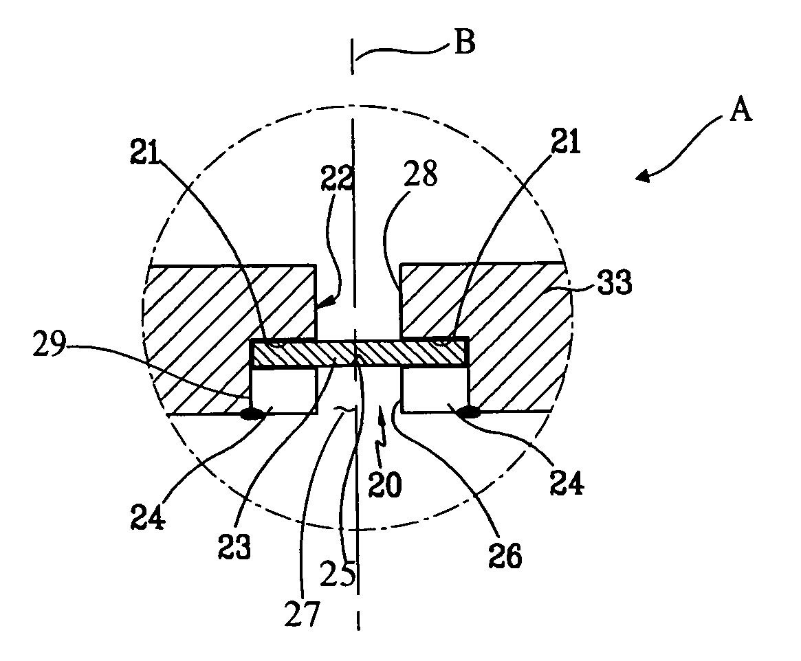
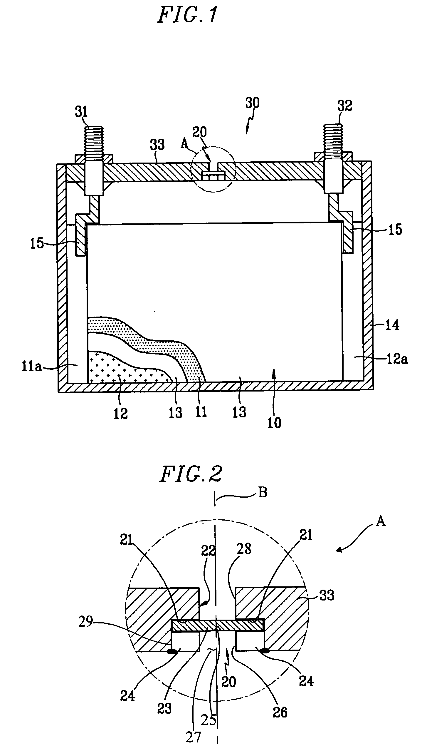
[0042]FIG. 1 is a cross sectional view of a secondary battery constructed as the present invention, and FIG. 2 is a cross sectional detail of the area A of FIG. 1 for the secondary battery illustrated by FIG. 1.

[0043] As shown in drawings, the secondary battery may be constructed with an electrode assembly 10 including a positive electrode 11, a negative electrode 12 and a separator 13 interposed between those two electrodes. Container 14 receives the electrode assembly 10 within its interior, and cap assembly 30 is fastened to container 14 in order to plug and seal an open end of container 14. Positive terminal 31 and negative terminal 32 extended outwardly through cap assembly 30 and are electrically connected to the positive and negative plates through taps 15. Safety valve 20 is mounted in cap assembly 30 to exhaust gas generated into the surrounding atmosphere inside container 14 by the battery.

[0044] Container 14 is made of an electrically conductive metal such as aluminum, a...

second embodiment

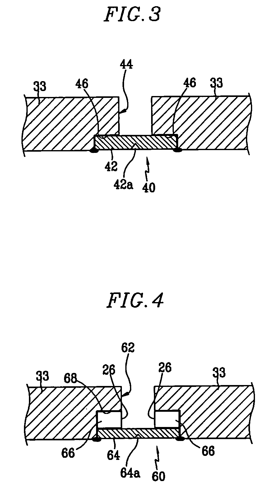
[0057]FIG. 3 illustrates second embodiment of the present invention, by showing a structure with a separately prepared safety valve 42 that is directly fixed to cap plate 33.

[0058] As shown in the drawing, safety device 40 of the present embodiment has a structure created by forming through hole 44 to perforated cap plate 33 in step process, and then inserting safety valve 42 which has been prepared separately from cap plate 33, against stepped surface 46 of hole 44 to be closely adhered, and welding adjoining portions of the peripheries of cap plate 33 and safety valve 42 by laser.

[0059] It is preferable that stepped surface 46 of hole 44 formed on cap plate 33 at a depth corresponding the thickness of the safety valve 42 so that the sides of cap plate 33 and safety valve 42 are fresh and lie in the same level when safety valve 42 is disposed in hole 44.

third embodiment

[0060]FIG. 4 is a schematic cross sectional view of a secondary battery constructed as the present invention. As shown in FIG. 4, safety device 60 of the present embodiment has a structure that may be fixed in plate by attaching fastening member 66 to one surface of safety valve 64 to be mounted in hole 62 formed in cap plate 33, inserting safety valve 64 and fastening member 66 to be placed on stepped surface 68 of hole 62, and welding adjoining peripheral portion of cap plate 33 and safety valve 64 such as with a laser.

[0061] It is preferably that stepped surface 68 formed by the step formation process and hole 62 have a round peripheral shape, and that fastening member 66 and safety valve 64 positioned against stepped surface 68 also have a conforming round peripheral shape with a size and combined thickness corresponding to the size and depth of the stepped surface 68.

[0062] Reference numerals 42a and 64a of FIGS. 3 and 4 which are not described above, identify grooves where sa...


PUM

PropertyMeasurementUnit
Thicknessaaaaaaaaaa
Pressureaaaaaaaaaa
Diameteraaaaaaaaaa

Abstract

A secondary battery may be manufactured with an electrode assembly having a positive electrode, a negative electrode, and a separator interposed between the positive electrode and the negative electrode. A container encases the electrode assembly. A hole formed on one end of the container with a stepped configuration that opens with different diameters on opposite sides of a cap plate and a safety valve mounted in the stepped surface of the hole, is configured to rupture and tear open upon occurrence of a predetermined internal battery pressure.

Description

CLAIM OF PRIORITY [0001] This application makes reference to, incorporates the same herein, and claims all benefits accruing under 35 U.S.C. 119 from an application earlier filed in the Korean Intellectual Property Office on 23 Jun. 2004 and 2 Jun. 2005 and there duly assigned Serial Nos. 10-2004-0047011 and 10-2005-0047230, respectively. BACKGROUND OF THE INVENTION [0002] 1. Field of the Invention [0003] The present invention relates to a secondary battery, and more particularly, to a secondary battery, a cap assembly thereof, and a method for easily mounting a safety valve in a safety cap assembly. [0004] 2. Description of the Related Art [0005] Unlike the primary battery, the secondary battery may be recharged. Non-aqueous electrolyte secondary batteries of high energy density have recently been developed as high power secondary batteries. Lower power batteries in which one battery cell is made into a battery pack are used as the power source for various portable electronic devic...

Claims


Application Information

Patent Timeline
IPC IPC(8): H01M2/08H01M2/12H01M10/04
CPCH01M2/1241Y10T29/49108H01M10/04Y02E60/10H01M50/3425Y02P70/50
Inventor KIM, YONG-SAMKIM, KI-HORYU, JAE-YULKIM, JAE-KYUNG
Owner SAMSUNG SDI CO LTD
Why Eureka
Try Eureka