Method and apparatus for determining a reference vehicle velocity and a rear wheel speed in a vehicle having three speed sensors

a technology of speed sensor and reference vehicle, which is applied in the direction of pedestrian/occupant safety arrangement, instruments, tractors, etc., can solve the problem that the dynamic control system does not address the roll of the vehicle, and achieve the effect of reducing the overall cost of the sensor set and increasing the accuracy of the reference velocity determination

Inactive Publication Date: 2005-12-29
FORD GLOBAL TECH LLC
View PDF20 Cites 40 Cited by
  • Summary
  • Abstract
  • Description
  • Claims
  • Application Information

AI Technical Summary

Benefits of technology

[0010] One advantage of the invention is the increased accuracy of the reference velocity determination. Once the reference velocity is determined, the rear wheel speeds of each of the rear wheels may be determined accurately. The rear wheel speed may take into account a slip effect, a yaw effect and / or both.
[0011] Another advantage of the invention is that the method set forth herein can handle large dynamic maneuvers and multiple wheel speeds that are in deep slip. This is important for dynamic control systems for which the wheel speeds of each of the rear wheels must be known.
[0012] Another advantage of the invention is that one less wheel speed sensor is required and, therefore, the cost of the overall sensor set is reduced.

Problems solved by technology

Typically, the dynamic control systems do not address roll of the vehicle.
In some systems, it may be desirable to reduce cost and not provide a separate wheel speed sensors, particularly for the rear wheels.

Method used


Image

  • Method and apparatus for determining a reference vehicle velocity and a rear wheel speed in a vehicle having three speed sensors
  • Method and apparatus for determining a reference vehicle velocity and a rear wheel speed in a vehicle having three speed sensors
  • Method and apparatus for determining a reference vehicle velocity and a rear wheel speed in a vehicle having three speed sensors

Examples


Embodiment Construction

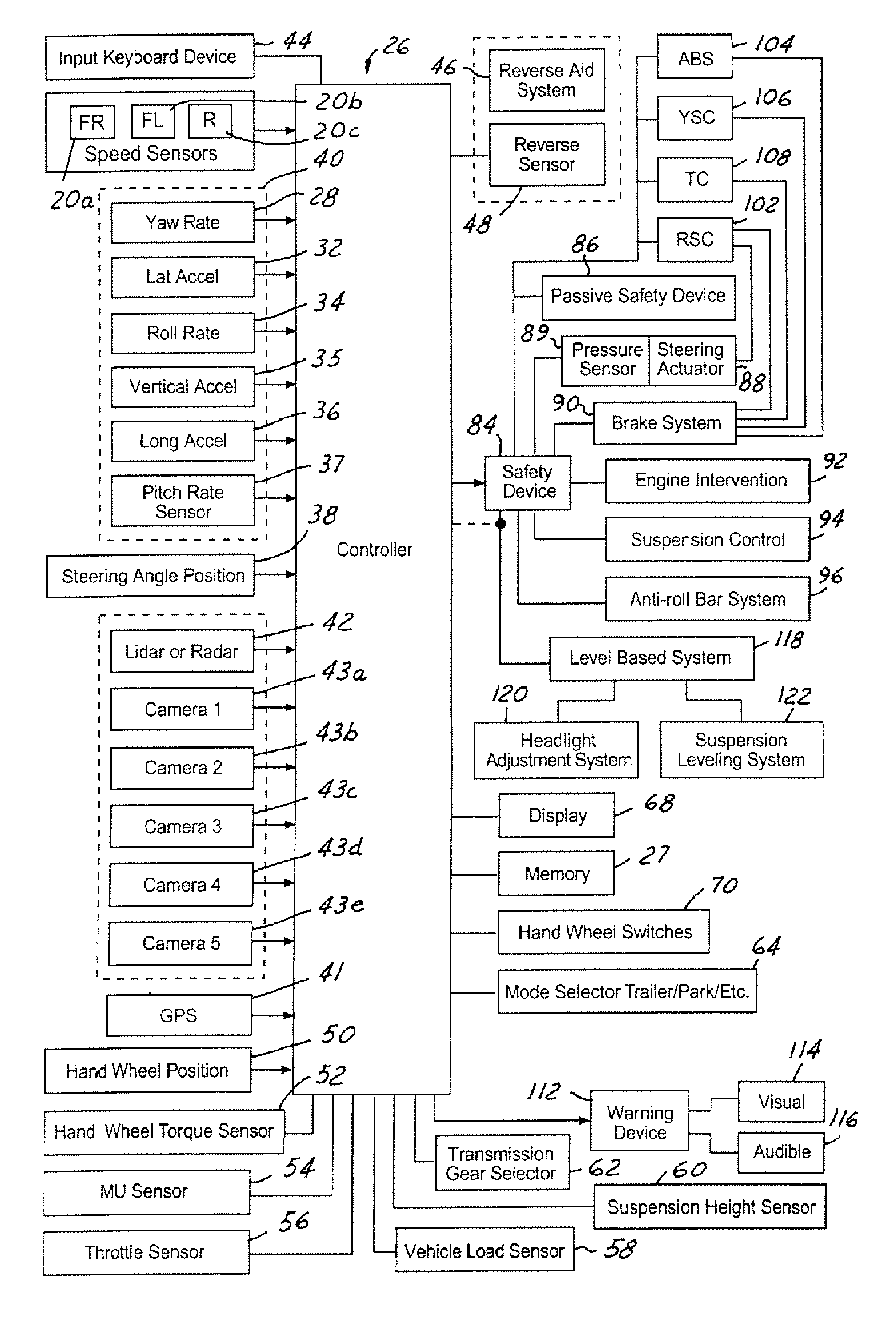
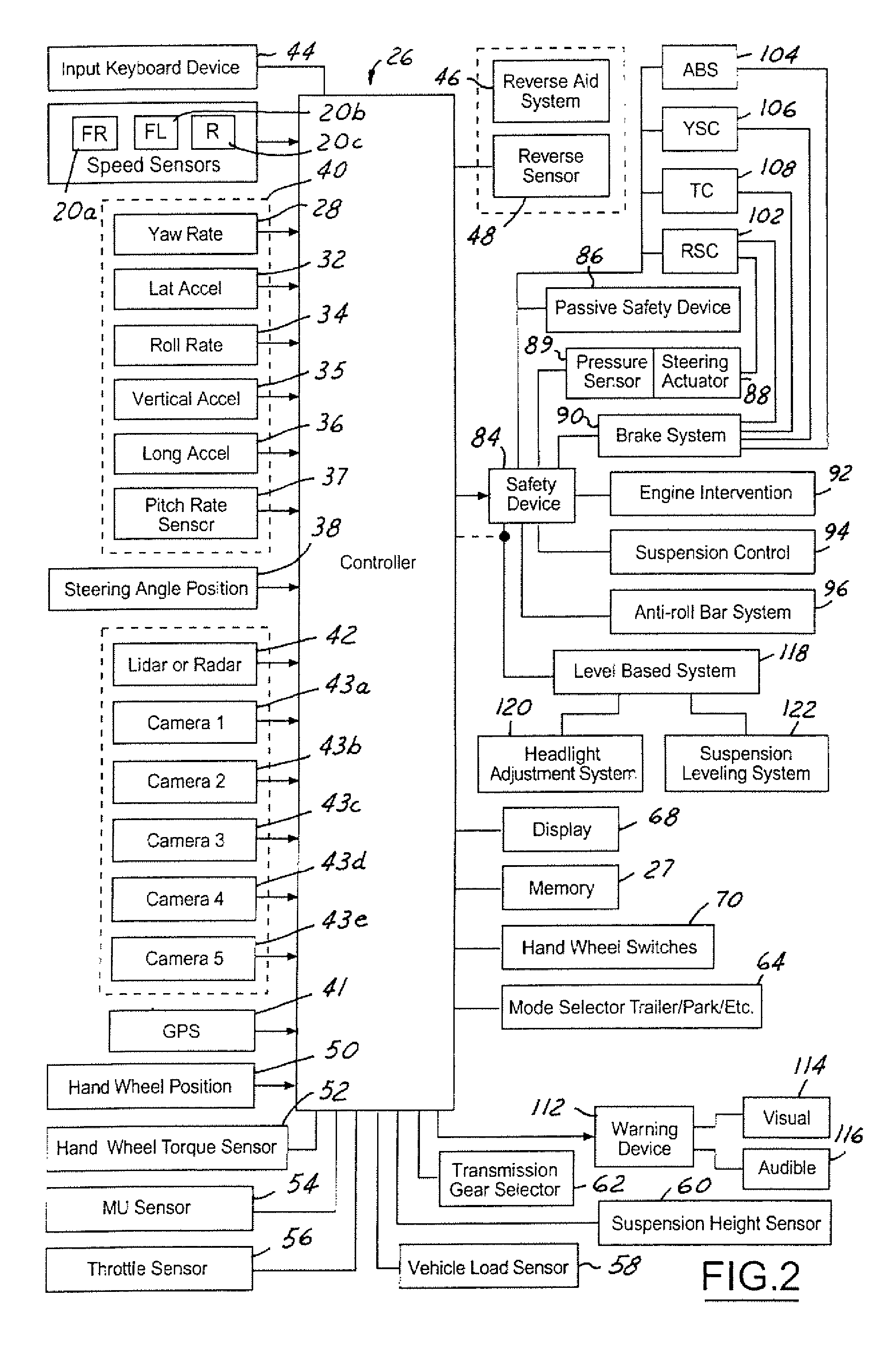
[0021] In the following figures, the same reference numerals will be used to identify the same components. The various terms and values are set forth by way of example and are not meant to be limiting unless specifically set forth in a claim. The following description is set forth with respect to an axle speed. However, other drive speeds may be used such as a driveshaft speed.

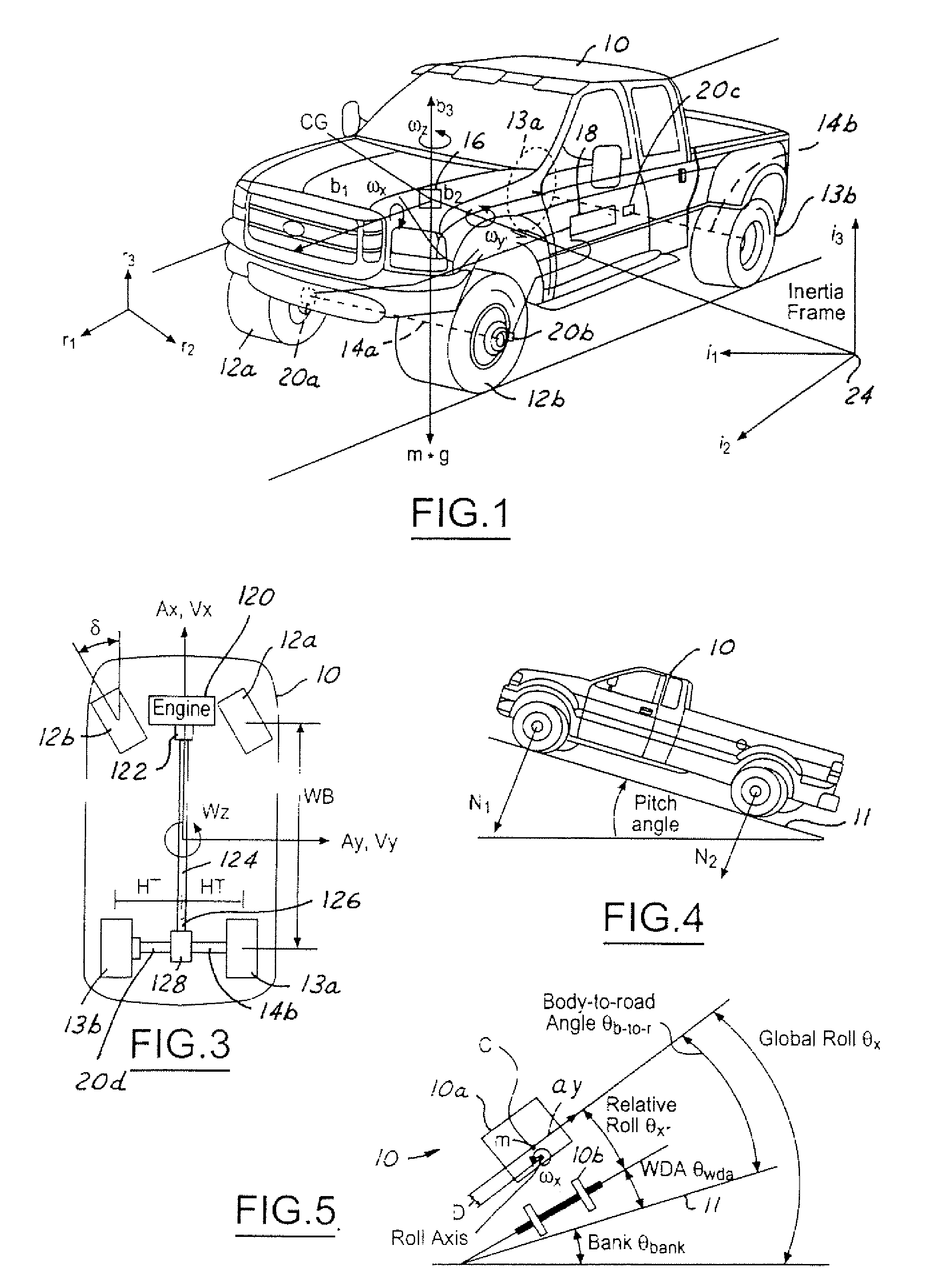
[0022] Referring to FIG. 1, an automotive vehicle 10 with a control system of the present invention is illustrated. Vehicle 10 has front right and front left tires 12a and 12b and rear right tires 13a and rear left tires 13a and 13b, respectively. The vehicle 10 may also have a number of different types of front steering systems 14a including having each of the front wheels configured with a respective controllable actuators and the front wheels having a conventional type system in which both of the front wheels are controlled together. The vehicle has a rear axle system 14b. Generally, the vehicle has a weig...


PUM


Abstract

The method for controlling a safety system (102-108) of a vehicle (10) determines a reference velocity from a first front wheel sensor (20A) and a second front wheel speed signal from a second front wheel sensor (20B). An axle speed sensor (20C) may be used to determine an axle speed signal. A first rear speed signal and a second rear speed signal are determined from the reference velocity, a slip effect and a yaw signal. The yaw signal may be determined from a yaw rate sensor (28). Safety system (102-108) may be controlled in response to the first rear wheel speed signal and the second rear wheel speed signal.

Description

BACKGROUND OF INVENTION [0001] The present invention relates generally to a dynamic control system for an automotive vehicle, and more particularly, to a system for determining a vehicle velocity. [0002] Dynamic control systems for automotive vehicles have recently begun to be offered on various products. Dynamic control systems typically control the yaw of the vehicle by controlling the braking effort at various wheels of the vehicle. By regulating the amount of braking at each corner of the vehicle, the desired direction of the vehicle may be maintained. [0003] Typically, the dynamic control systems do not address roll of the vehicle. For high profile vehicles in particular, it would be desirable to control the rollover characteristics of the vehicle to maintain the vehicle position with respect to the road. That is, it is desirable to maintain contact of each of the four tires of the vehicle on the road. [0004] Vehicle rollover and tilt control (or body roll) are distinguishable ...

Claims


Application Information

Patent Timeline
Patent Type & Authority Applications(United States)
IPC IPC(8): B60T8/172B60T8/1755
CPCB60G17/018G06F17/00B60G2400/0523B60G2400/204B60G2400/208B60G2400/61B60G2800/01B60G2800/019B60G2800/702B60Q2300/132B60T8/172B60T8/1755B60T2230/03B60T2240/06B60T2250/04B60G17/01933
Inventor BREWER, MICHAELBROWN, TODDSALMON, THOMAS
Owner FORD GLOBAL TECH LLC
Why Eureka
Try Eureka