Method of making motion picture release-print film

a technology of releaseprint and motion picture, applied in the field of motion picture film, can solve the problems of anamorphic process, relatively expensive process, and audience dislike of the seams between the three, and achieve the effect of enhancing the projected image, and reducing the waste of film

Inactive Publication Date: 2006-01-05
GOODHILL DEAN K +1
View PDF3 Cites 0 Cited by
  • Summary
  • Abstract
  • Description
  • Claims
  • Application Information

AI Technical Summary

Benefits of technology

[0020] The present invention provides a method of making motion picture release-print film that has an enhanced projected image with a minimum of film waste. The film has an enhanced projected image due to an increased frame size relative to prior film formats, while, at the same time, in one embodiment, significantly reducing the cost of production and distribution by reducing the quantity of film required for each print. Thus, at least one embodiment of the invention reconciles two conflicting parameters in film making—enhancing the projected film image and minimizing film waste. Both embodiments significantly increase the clarity and resolution of the projected image.
[0022] In one embodiment, the 1.85:1 aspect ratio is maintained in a three perforation format, but with a significantly enlarged frame size. The width of each frame is expanded such that it occupies substantially all of the space between the perforations that is available for the projected image. The height of the frame is then increased until the width-to-height (aspect) ratio of the frame equals 1.85:1. The result is a significantly enlarged frame that provides an enhanced projected image, due to the enlarged size of the frame, as compared to the prior art 1.85:1 projection formats having a smaller frame size. Yet, the frame only occupies slightly less than three perforations of film height. Consequently, the film can be exhibited at a rate of 67.5 feet-per-minute, at 24 frames-per-second. Importantly, film waste is minimized, while the enhancement of the projected image is maximized. Moreover, since the 1.85:1 aspect ratio is maintained, all of the advantages attendant to that aspect ratio, which is the predominant projection format in the United States and Canada, are maintained.
[0023] In another embodiment, an aspect ratio of 2.0:1 has been established in a four perforation format. As in the first embodiment, a significantly enlarged frame size is provided to yield an enhanced projected image. In this second embodiment, the height of the frame is expanded until the frame-to-frame spacing is reduced to substantially zero, with each frame spanning exactly four perforations. The width of the frame is then increased as much as possible until it substantially occupies all of the space between the perforations that is available for the projected image. An anamorphic process can be used to laterally “squeeze” the projected image to fit the available space between the perforations, to yield a width-to-height (aspect) ratio of 2.0:1. Again, the result is a frame with an enhanced projected image due to the increase in the size of the frame. Although the frame occupies four perforations, the enhancement in the projected image is substantial and significant. Moreover, there is virtually no wasted space between frames and, thus, substantially all of the film emulsion area available for a photographic image is used. Once again, film waste is minimized, while the enhancement of the projected image is maximized. Furthermore, since the majority of film projection systems for theatrical film exhibition operate at 90 feet-per-minute, 24 frames per second, the new 2.0:1 projection format provided by the present invention is adapted for use with these projection systems, with some slight modifications, as will be described in more detail below.
[0024] Hence, in both of the formats disclosed herein, the end result of the increase in image area is an improvement in the clarity of the image projected on the large screen, with minimum film waste. In addition, in the second embodiment, an aspect ratio of 2.0:1 has been established to be proposed as an alternate release print format which conveniently corresponds to the proposed broadcast format for the fixture High Definition TV.

Problems solved by technology

But some audiences disliked the seams where the three images joined together on the screen.
Also, it was a relatively expensive process, both in terms of production and distribution.
However, there are still many inherent drawbacks to the anamorphic process, including limited photographic depth-of-field and large, heavy camera lenses.
Further, some film makers feel that the 2.35:1 aspect ratio is simply too wide.
Moreover, the anamorphic process results in an image that is so wide that much of it cannot be shown on television absent significant cropping of the image or presentation of the image in what has come to be known as a “letterbox.”
Unfortunately, the economic consequences associated with 1.85 format are considerable.
Although both the three-perforation format and the 2.5-perforation format help reduce film waste, neither one provides any enhancement in the quality or resolution of the projected image.
However, the basic specification of the projection pull-down has failed to evolve in response to these changes.

Method used


Image

  • Method of making motion picture release-print film
  • Method of making motion picture release-print film
  • Method of making motion picture release-print film

Examples


Embodiment Construction

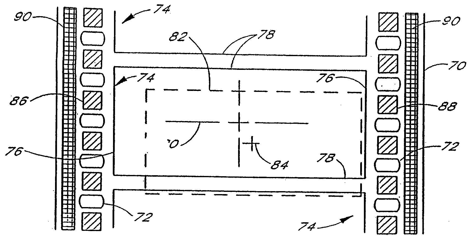
[0032] The first embodiment of the present invention, which is referred to as “MaxiVision,” is shown in FIG. 3. It comprises a strip of 35 mm motion picture film 70 having its entire surface coated with a light sensitive emulsion. Two rows of perforations 72 extend along opposite edges of the film for engagement with the sprockets of a film projection system. Images are exposed onto the film, with the images being defined by a series of frames 74 having a significantly enlarged size.

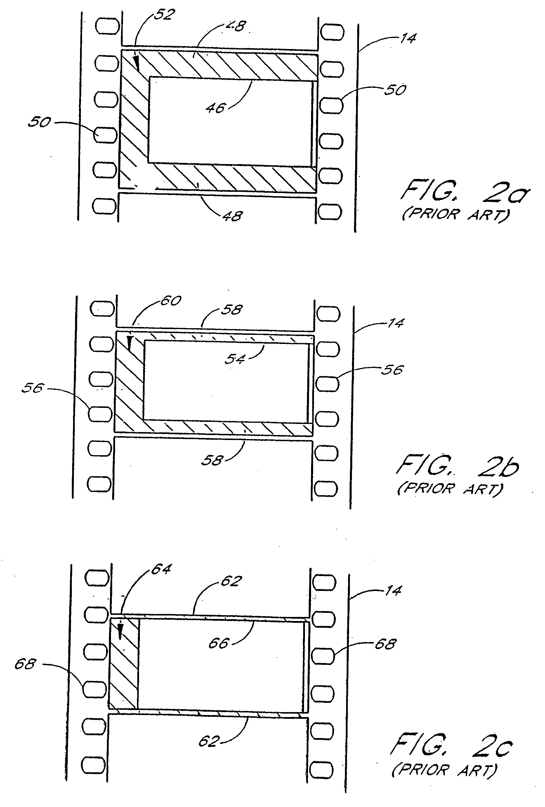
[0033] In accordance with the invention, the height 76 of each frame 74 spans three perforations 72. This eliminates the wasted area between frames that currently exists in the 1.85:1 / four-perforation projection format, as previously described in conjunction with FIG. 2a. As a result, the print film consumption and processing costs for MaxiVision are reduced by 25%, without sacrificing image size in any way. Furthermore, an increase in projectable image size is achieved by allowing the permissible image...


PUM


Abstract

A method of making motion picture release-print film, such as 35 mm film. The film has an enlarged frame that occupies substantially the entire width of the film that is available for the exposure of images, and the spacing between frames is minimized. Film having these enlarged frames provides an enhanced image with a minimum of film waste. Aspect ratios of 1.85:1 and 2.01:1 in the enlarged frame size are contemplated in three and four perforation formats. A digital soundtrack or other appropriate soundtrack replaces the analog soundtrack that occupies a portion of the available width. The soundtrack may provide for redundancy.

Description

BACKGROUND OF THE INVENTION [0001] The present invention relates to motion picture film and, more particularly, a method of making motion picture release-print film that provides an enhanced projected image and lower film consumption. [0002] With reference to FIG. 1, a conventional motion picture projector 10 uses reels 12 that supply the film 14 that goes into the projection system, and reels 16 that take up the film which has already been projected. A more recent design uses “platters” (large horizontal reels) that, on alternate ends, serve to both supply and take-up the film. Between the supply reel 12 and the take-up reel 16 lies an optical / mechanical device that actually projects the images that comprise what we call “motion pictures.” This device is referred to as the projector head 18. Behind the head 18 is a lamp house 20 and a light-condenser 22, and in front of the head are lenses 24 that focus the “moving” image onto a projection screen. [0003] Below the head 18 are sound...

Claims


Application Information

Patent Timeline
Patent Type & Authority Applications(United States)
IPC IPC(8): G03B27/32G03B31/02
CPCG03B1/42G03B2217/243G03B31/02G03B19/18
Inventor GOODHILL, DEAN K.BEHRNS, DON P.
Owner GOODHILL DEAN K
Why Eureka
Try Eureka