Physical information acquisition method, a physical information acquisition apparatus, and a semiconductor device

a technology of physical information acquisition and acquisition apparatus, which is applied in the direction of color television details, television systems, radio control devices, etc., can solve the problems of increasing the length of the control line for controlling the reading of pixel signals, increasing the load imposed on the driver connected to the control line, and increasing the skew

Inactive Publication Date: 2006-01-05
SONY CORP
View PDF14 Cites 43 Cited by
  • Summary
  • Abstract
  • Description
  • Claims
  • Application Information

AI Technical Summary

Benefits of technology

[0022] The present invention provides a first physical information acquisition method of reading unit-element signals from a semiconductor device, the semiconductor device including unit elements arranged in a particular order, each unit element having a unit-element signal generation part for outputting a unit-element signal indicating a detected change in a physical quantity, wherein a control line for driving unit elements to read unit-element signals from the respective unit elements is driven at a dividing point on the control line, and more preferably at a plurality of dividing points on the control line.
[0023] The present invention provides a second a physical information acquisition method, in which a control line is driven at an original driving point that results in a reduction in a maximum value of a product of load

Problems solved by technology

The increase in the number of pixel transistors and an increase in the number of functions achieved by the capability of accessing arbitrary pixels result in an increase in the length of control lines for controlling reading of pixel signals.
This causes an increase in load imposed on drivers connected to the control lines and also causes an increase in skew, which cannot be neglected.
Accordingly skew caused by the difference in locations of pixels along these control signal lines or the horizontal s

Method used


Image

  • Physical information acquisition method, a physical information acquisition apparatus, and a semiconductor device
  • Physical information acquisition method, a physical information acquisition apparatus, and a semiconductor device
  • Physical information acquisition method, a physical information acquisition apparatus, and a semiconductor device

Examples


first embodiment

[0101]FIG. 3 shows a manner in which driving buffers are disposed so as to reduce skew (hereinafter, the technique will be referred to as a skew reduction layout technique) according to a first embodiment of the invention. FIG. 4 shows a comparative example in which driving is performed at one end, and FIG. 5 shows another comparative example in which driving is performed at both ends.

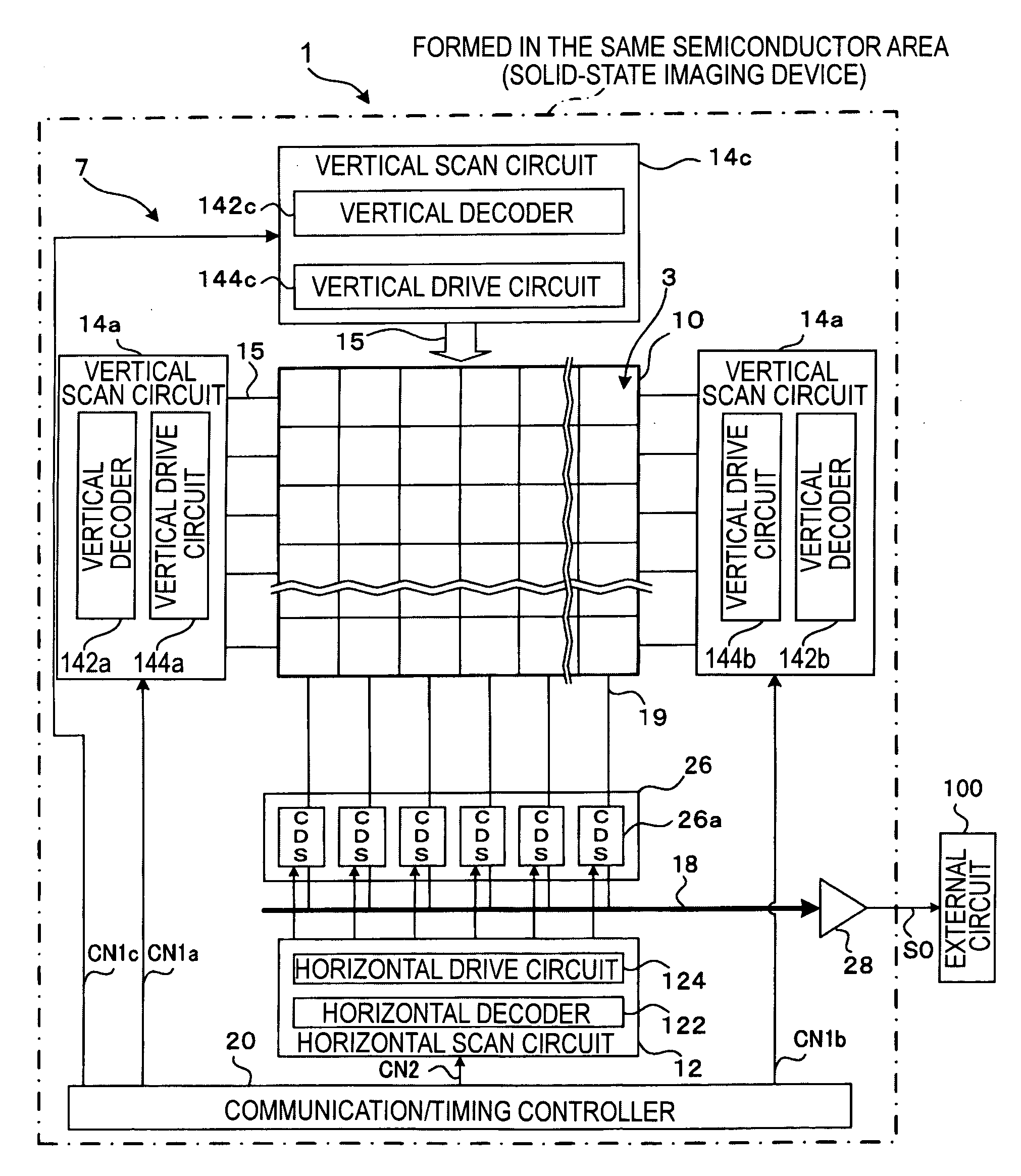
[0102] When a vertical driving circuit 144 (that is, a driving buffer BF) is disposed at only one side of the pixel array part 10 as in the case of the configuration shown in FIG. 4(A), the load increases as the number of pixels is increased to achieve higher resolution. The increase in the load results in an increase in the difference in reading time between a pixel located close to the driving buffer and a pixel located far from the driving buffer. This can make it difficult to correctly read pixel signals, and can cause shading or noise.

[0103] If the total line resistance is denoted by R and the t...

second embodiment

[0119]FIG. 7 shows a skew reduction layout technique according to a second embodiment of the invention. In this second embodiment, two ends of the control line are not used as original driving points, but original driving points are set at three dividing points of the control line such that points farthest from the respective driving points within the range in which skew is to be suppressed are distributed substantially equally. Hereinafter, this driving method will be referred to as the “three-dividing-point equal driving method”.

[0120] To set three original driving points such that points farthest from the respective original driving points within the range in which skew is to be suppressed are equally distributed, the distance between each point farthest from the corresponding original driving point is set to be ⅙ of the total length of the control line as shown in FIG. 7.

[0121] In this case, if the total line resistance is denoted as R and the total parasitic capacitance is de...

third embodiment

[0125]FIG. 8 shows a skew reduction layout technique according to a third embodiment of the invention. In this third embodiment, in addition to three original driving points on the control line two of which are located at points whose distance from a closer end of the control line is ¼ of the total length of the control line and the other one of which is located at the center of the control line, original driving points are set at two respective end points of the control line. Hereinafter, this driving method will be referred to as the “both-end and three-dividing-point equal driving method”.

[0126] In this case, as shown in FIG. 8, if the total line resistance is denoted as R and the total parasitic capacitance is denoted as C, the line resistance and the parasitic capacitance at the points farthest from the respective original driving points are respectively given by R / 8 and C / 8, and thus the time constant τe in the “both-end and three-dividing-point equal driving method” is given...


PUM


Abstract

In particular for a solid-state image sensor with high resolution, a control line is not driven at any of two end points of the control line, but the control line is driven at two arbitrary dividing points on the control line. Preferably, two points on control line whose distance from a closer end of a range in which skew is to be suppressed is equal to ¼ of the total length of the range may be selected as the dividing points at which the control line is driven. In this case, the time constant at points farthest from the driving points becomes ¼ of that which occurs when the control line is driven at both end points thereof and 1/16 of that which occurs when the control line is driven at one end point thereof, and thus, theoretically, the skew can be reduced to ¼ or 1/16 of that which occurs when the control line is driven at both end points or only one end point.

Description

CROSS REFERENCE TO RELATED APPLICATIONS [0001] The present invention contains subject matter related to Japanese Patent Application JP 2004-195502 filed in the Japanese Patent Office on Jul. 1, 2004, the entire contents of which are incorporated herein by reference. BACKGROUND OF THE INVENTION [0002] The present invention relates to a physical information acquisition method, a physical information acquisition apparatus, and a semiconductor device. More particularly, the present invention relates to a driving control technique in reading unit-element signals from unit elements, particularly suitable for use in a semiconductor device, such as a solid-state image sensor including an array of unit elements sensitive to an electromagnetic wave such as light or radiation incident from the outside and capable of outputting an electrical signal indicating a physical quantity distribution detected by the unit elements. [0003] In various applications, to detect a physical quantity distributio...

Claims


Application Information

Patent Timeline
IPC IPC(8): H04N1/04H01L27/146H04N5/335H04N5/361H04N5/369H04N5/376
CPCH04N5/3653H04N5/369H04N5/3765H04N25/672H04N25/70H04N25/745H04N25/76H04N25/77
Inventor OKANO, MASAFUMIUI, HIROKI
Owner SONY CORP
Why Eureka
Try Eureka