Image display device and portable terminal device

Active Publication Date: 2006-01-05
NEC LCD TECH CORP
View PDF8 Cites 22 Cited by
  • Summary
  • Abstract
  • Description
  • Claims
  • Application Information

AI Technical Summary

Benefits of technology

[0047] The focal distance f may be shorter than the distance between the lenticular lens and the pixels. This would enable the focal positions of the lens to be set closer than the pixels toward the lens, and accordingly a broader range of light rays to be used on the illuminating member. As a result, the distance between adjoining convexes may be extended, and therefore the image display device can be reduced in thickness without sacrificing its display quality because it can serve to reduce the influence of the directionality distribution of emitted lights attributable to

Problems solved by technology

In view of the foregoing and other exemplary problem, the present inventors tried a reduction in the distance between the pixels and the backlig

Method used


Image

  • Image display device and portable terminal device
  • Image display device and portable terminal device
  • Image display device and portable terminal device

Examples


first exemplary embodiment

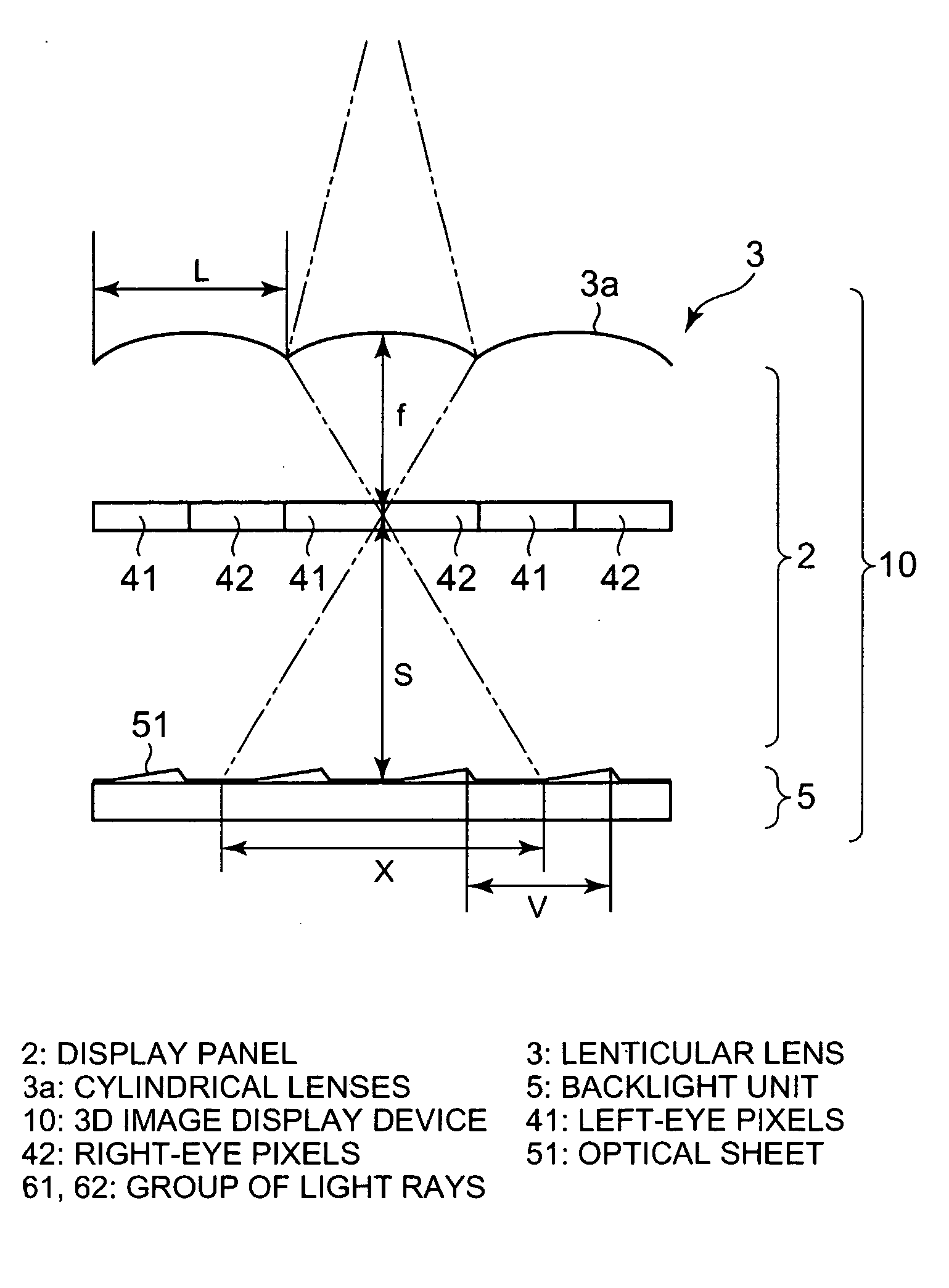
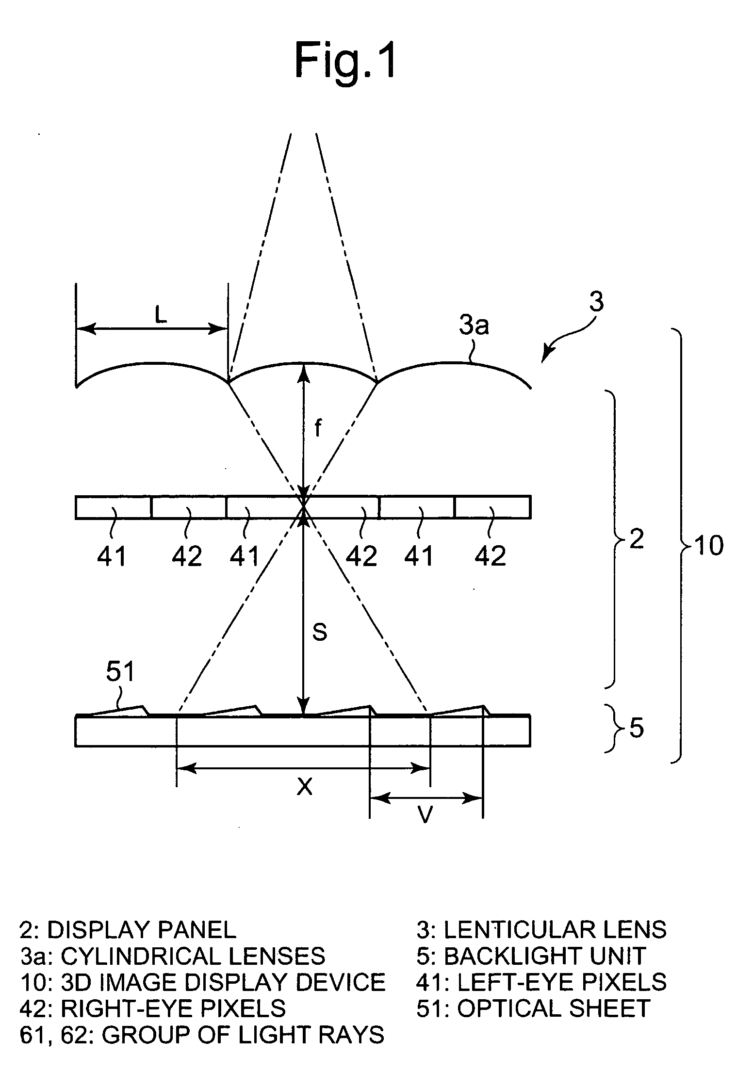
[0068] Image display devices, which are exemplary embodiments of the present invention, will be described below in specific terms with reference to the accompanying drawings. First will be described a three-dimensional image display device, which is a first exemplary embodiment of the invention. FIG. 1 shows an optical model of the three-dimensional image display device embodying the invention in this mode. In FIG. 1, illustration of other constituent elements than pixels in the display panel is dispensed with in order to make the drawing easier to perceive.

[0069] As shown in FIG. 1, in the three-dimensional image display device 10 embodying the invention in this mode, a lenticular lens 3, a display panel 2 and a backlight unit 5 are disposed in this order away from the viewer. The display panel 2 in this image display device 1 may be a transmissive liquid crystal panel for instance, and the display pixels on the display panel may include mutually adjoining right-eye pixels 42 and ...

second exemplary embodiment

[0090] Next will be described a three-dimensional image display device, according to the second exemplary embodiment of the present invention. FIG. 3 is an optical model diagram illustrating the three-dimensional image display device embodying the invention in this mode, and FIG. 4 shows a perspective view of a fly-eye lens. As shown in FIG. 3, a three-dimensional image display device 20 of this exemplary embodiment is the same as the three-dimensional image display device 10 of the first exemplary embodiment described above except that a fly-eye lens 8 in which constituent lenses are formed in a matrix shape is used instead of the lenticular lens. As the three-dimensional image display device 20 of this exemplary embodiment uses the fly-eye lens 8, it is possible to distribute the lights of pixels transmitted through the lenses in four directions, up and down, and right and left. As a result, even if the arranging direction of the three-dimensional image display device 20 is turned...

third exemplary embodiment

[0094] Next will be described a three-dimensional image display device, which is a third exemplary embodiment of the present invention. FIG. 5 shows a partial perspective view of the three-dimensional image display device, according to the third exemplary embodiment of the invention. Incidentally, FIG. 5 shows only part of the lenticular lens, part of the optical sheet and one pair of display pixels, but the illustration of all other constituent elements is dispensed with.

[0095] As shown in FIG. 5, in a three-dimensional image display device 30 of this exemplary embodiment, the lengthwise direction of the cylindrical lenses 3a forming the lenticular lens 3 is not identical with the direction in which prismatic convexes formed on the surface of the optical sheet 51 extend. The repeating pitch V of the convexes on the optical sheet 51 satisfies the condition of the following Formula 26, where θ is the angle formed by the lengthwise direction of the cylindrical lenses 3a with the exte...


PUM


Abstract

An image display device is including a display panel in which a plurality of display units including at least pixels for displaying an image for a first point of view and a second point of view are arrayed in a matrix shape, a lens for distributing lights transmitted through pixels for the first point of view and lights transmitted through pixels for the second point of view into mutually different directions, and an illuminating member which is arranged on a back of the display panel and on whose face toward the display panel a plurality of convexes or concaves are formed, wherein a following formula is satisfied regarding the distance V between adjoining convexes or concaves in the illuminating member, where S is the distance between the pixels and the convexes or concaves, f is the focal distance of the lens, and L is the array cycle of the lens.
V≦L×S/f

Description

BACKGROUND OF THE INVENTION [0001] 1. Field of the Invention [0002] The present invention relates to an image display device capable of displaying an image toward a plurality of points of view and a portable terminal device mounted with this image display device. [0003] 2. Description of the Related Art [0004] Attempts have been made to develop an image display device capable of displaying different images toward a plurality of points of view. One example is a three-dimensional image display device. The three-dimensional image display device displays parallax images for the right eye and left eye, and a viewer looking with both eyes at the images differentiated between right and left can perceive a three-dimensional image. [0005] To realize this function concretely, many three-dimensional image display systems have been studied. Three-dimensional image display systems can be broadly classified into two types, one using glasses and the other using no glasses. The former can be furthe...

Claims


Application Information

Patent Timeline
IPC IPC(8): G02B27/10G02B30/27
CPCG02B27/2214H04M1/0214G02F1/133526G02B30/27
Inventor UEHARA, SHIN-ICHIIKEDA, NAOYASUTAKANASHI, NOBUAKI
Owner NEC LCD TECH CORP
Why Eureka
Try Eureka