Transmission type screen

a technology of transmission screen and screen body, which is applied in the direction of optics, instruments, projectors, etc., can solve the problems of glare of external light and the like occurring on the surface of the front sheet, image quality is deteriorated, image quality is greatly deteriorated, etc., and achieves the effect of convenient manufacturing and desired optical performan

Inactive Publication Date: 2006-01-05
DAI NIPPON PRINTING CO LTD
View PDF5 Cites 8 Cited by
  • Summary
  • Abstract
  • Description
  • Claims
  • Application Information

AI Technical Summary

Benefits of technology

[0006] An object of the present invention, which has been made to solve the above problems, is to provide a transmission type screen that can suppress deterioration of image quality due to the glare distortion of external light and the like occurring on a screen surface while keeping a feeling (glossy feeling of image) as if a CRT-TV is directly viewed.
[0010] According to the present invention, the smooth surface having the surface roughness Ra of 0 μm≦Ra≦0.5 μm is formed on the viewer side surface of the nearest-to-viewer side screen member, which is located nearest to the viewer side, of the plurality of screen members constituting the transmission type screen, as well as the amount of warping D of the nearest-to-viewer side screen member is set to −10 mm≦D≦15 mm. Accordingly, deterioration of image quality due to the glare distortion of external light and the like occurring on the screen surface can be suppressed while keeping the feeling as if the CRT-TV is directly viewed (glossy feeling of image).
[0013] In the present invention, the amount of warping of the screen member, which is located nearest to the light source side, of the plurality of screen members is preferably equal to or less than the amount of warping D of the nearest-to-viewer side screen member. With this arrangement, it is possible to press the overall transmission type screen from both the sides thereof by both the screen members located nearest to the light source side and to the viewer side. Accordingly, the screen member located between both the screen members is sandwiched therebetween so that these screen members can be made to a single sheet. Therefore, it is possible to prevent spaces from being formed between the respective screen members constituting the transmission type screen, thereby deterioration of image quality due to the spaces can be effectively prevented.
[0016] Further, it is preferable that the nearest-to-viewer side screen member be arranged by bonding a member for forming the smooth surface and a member for forming the lenticular lens group with each other. With this arrangement, it is possible to add desired optical performances by forming the smooth surface and the lenticular lens group on a different member, respectively, thereby the screen member as described above can be easily manufactured.
[0018] It is preferable that the smooth surface be formed on the overall viewer side surface of the nearest-to-viewer side screen member. With this arrangement, a more glossy feeling can be obtained. Further, it is preferable that the nearest-to-viewer side screen member be arranged by bonding a member for forming the smooth surface and a member for forming the fly eye lens group with each other. With the above arrangement, it is possible to add desired optical performances by forming the smooth surface and the fly eye lens group on a different member, respectively, thereby the screen member as described above can be easily manufactured.
[0019] Further, in the present invention, it is preferable that a reflection preventing layer (an antireflection layer) be formed at least on the light outgoing portions, through which image light is transmitted, of the nearest-to-viewer side screen member. With this arrangement, the intensity of the glare of external light and the like occurring on the viewer side uppermost surface can be lowered, which permits to appropriately control the degree of glare according to a necessary and desired glossy feeling. Even in this case, an uncomfortable feeling felt by the viewer as to glare is caused by that he or she observes glare having distortion different from that of an image by overlapping the glare on the image. Accordingly, it is still preferable to take the amount of warping D of a screen member into consideration even in the screen member which can reduce the intensity of glare by forming the reflection preventing layer.

Problems solved by technology

In the transmission type screen using the front sheet described above, however, when the front sheet is deformed, the glare of the external light and the like occurring on the surface of the front sheet is also distorted.
In this case, a problem arises in that the image quality is greatly deteriorated because a very uncomfortable feeling is given to the viewer.
However, this method is disadvantageous in that the feeling of an image as if the CRT-TV is directly viewed, which is obtained by the smooth surface of the front sheet, is naturally lost, from which a problem arises in that the image quality is deteriorated in this point of view.

Method used


Image

  • Transmission type screen
  • Transmission type screen
  • Transmission type screen

Examples


example 1

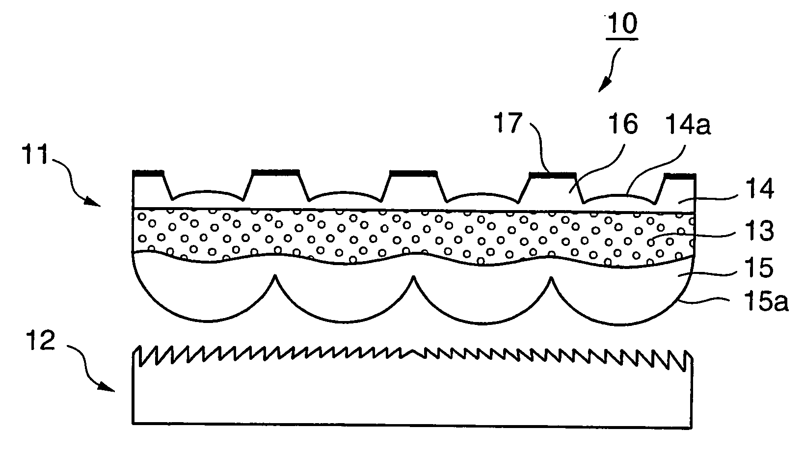
[0081] A transmission type screen corresponding to that shown in FIG. 1 was manufactured as a transmission type screen according to example 1.

[0082] Specifically, a 52-inch double-sided lenticular lens sheet having a light diffusion layer as an intermediate layer as well as clear layers on the front and back surfaces thereof was manufactured by the multi-layer extrusion molding method. The light diffusion layer was composed of an acrylic resin (refraction factor: 1.49) as a base member which contained therein, as a light diffusion agent, 2 wt % of beads composed of a spherical bridged acryl-styrene copolymer resin having an average particle size of 20 μm and a refraction factor of 1.51 as well as 3.5 wt % of spherical bridged styrene beads having an average particle size of 9 μm and a refraction factor of 1.59. The front and back clear layers were composed of a transparent acrylic resin, and lenticular lens groups extending in a vertical direction were formed on the light source si...

example 2-1

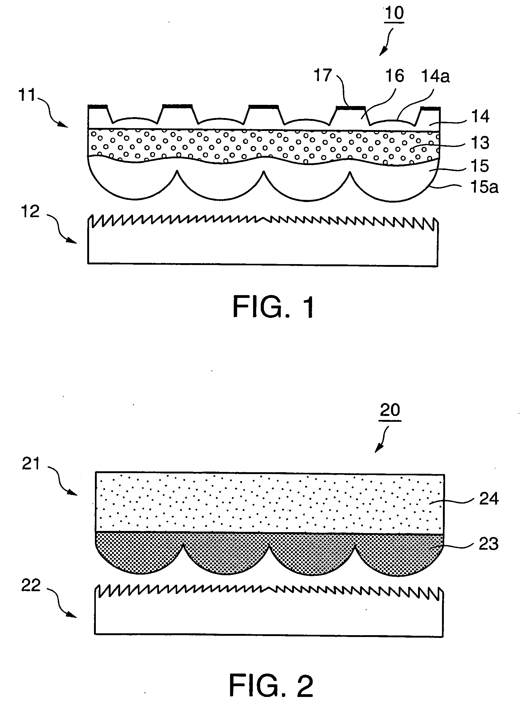
[0086] A transmission type screen corresponding to that shown in FIG. 2 was manufactured as a transmission type screen according to example 2-1.

[0087] Specifically, a 60-inch single-sided lenticular lens sheet, which had light diffusion layers on the viewer side and on the light source side, respectively, was manufactured by the multi-layer extrusion molding method. The viewer-side light diffusion layer was composed of an acrylic resin (refraction factor: 1.49) as a base member which contained therein, as a light diffusion agent, 0.4 wt % of beads composed of a spherical bridged acryl-styrene copolymer resin having an average particle size of 5 μm and a refraction factor of 1.51. Further, the light source side light diffusion layer was composed of an acrylic resin (refraction factor: 1.49) as a base member which contained therein, as a light diffusion agent, 5.5 wt % of spherical bridged styrene beads having an average particle size of 9 μm and a refraction factor of 1.59. A lentic...

example 2-2

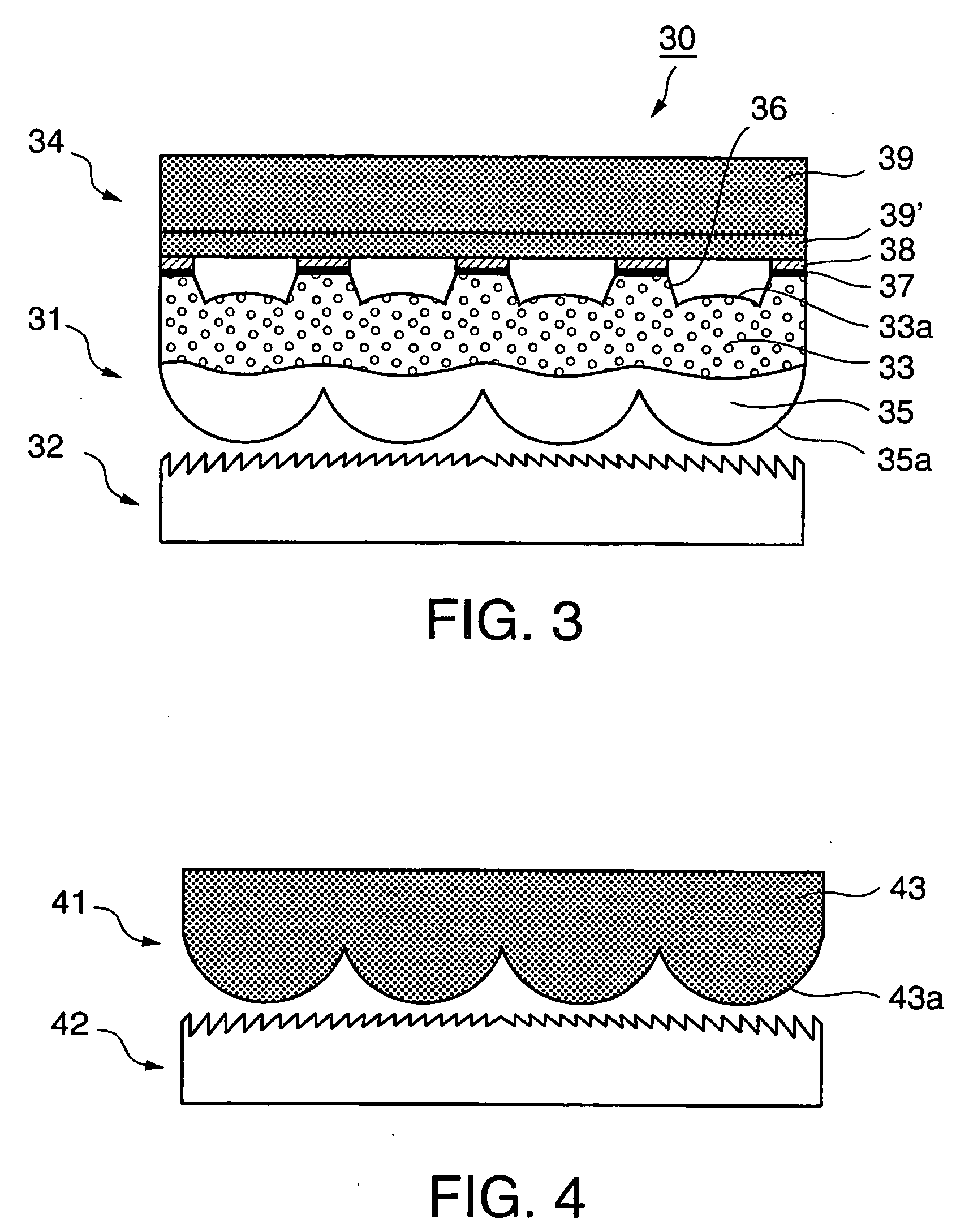
[0091] A transmission type screen corresponding to that shown in FIG. 4 was manufactured as a transmission type screen according to example 2-2.

[0092] Specifically, a 60-inch single-sided lenticular lens sheet having a light diffusion layer was manufactured by the cast molding method. The light diffusion layer was composed of an acrylic resin (refraction factor: 1.49) as a base member which contained therein, as a light diffusion agent, 2.5 wt % of beads composed of a spherical bridged acryl-styrene copolymer resin having an average particle size of 13 μm and a refraction factor of 1.53 as well as 5 wt % of spherical bridged styrene beads having an average particle size of 9 μm and a refraction factor of 1.59. A lenticular lens group, which extended in the vertical direction at a pitch of 0.15 mm, was formed on the light source side surface of the light diffusion layer.

[0093] The 60-inch transmission type screen was assembled by further disposing a Fresnel lens sheet having the sa...


PUM


Abstract

There is provided a transmission type screen that can suppress deterioration of image quality due to glare distortion of external light and the like that occurs on a screen surface while keeping a feeling (a glossy feeling of an image) as if a CRT-TV is directly viewed. The transmission type screen 10 is arranged by combining a plurality of screen members (for example, a lenticular lens sheet 11 and a Fresnel lens sheet 12), which realize various optical functions such as transmission, diffusion, condensing and the like of light, with each other. A smooth surface having a surface roughness Ra of 0 μm≦Ra≦0.5 μm is formed on the viewer side surface of a nearest-to-viewer side screen member (for example, the lenticular lens sheet 11) of the plurality of screen members, as well as the amount of warping D of the nearest-to-viewer side screen member (for example, the lenticular lens sheet 11) is −10 mm≦D≦15 mm.

Description

TECHNICAL FIELD [0001] The present invention relates to a transmission type screen used as a component of a rear projection type projection system such as projection television and the like. More particularly, the present invention relates to a transmission type screen giving a glossy feeling to an image making use of the glare of external light and the like occurring on the outermost surface on a viewer side. BACKGROUND ART [0002] At present, an arrangement, in which a Fresnel lens sheet and a lenticular lens sheet are disposed in this order from a light source side, is ordinarily used as the transmission type screen. Further, recently, an arrangement, in which a transparent front sheet or a front sheet subjected to coloring processing is disposed on the viewer side of a lenticular lens sheet, is also used (refer to Japanese Patent Application Laid-Open Publications Nos. 7-248537 and 8-137010 (patent documents 1 and 2)). [0003] Incidentally, in the transmission type screen using th...

Claims


Application Information

Patent Timeline
Patent Type & Authority Applications(United States)
IPC IPC(8): G02B27/10G02B3/00G03B21/62G03B21/625
CPCG02B3/0031G03B21/625G02B3/0062G02B3/0056G02B3/00G02B3/06G03B21/602
Inventor MIYATA, HIDEKI
Owner DAI NIPPON PRINTING CO LTD
Why Eureka
Try Eureka