Perpendicular magnetic recording head having main magnetic pole layer formed on high-flatness surface, and method of manufacturing the head

a perpendicular magnetic and recording head technology, applied in the field of perpendicular magnetic recording head and a manufacturing method, can solve the problems of inability to adapt to a higher recording density, process difficulty in extremely reducing the width size, etc., and achieve the effect of higher pattern accuracy

Inactive Publication Date: 2006-01-05
TDK CORPARATION
View PDF19 Cites 7 Cited by
  • Summary
  • Abstract
  • Description
  • Claims
  • Application Information

AI Technical Summary

Benefits of technology

[0018] With the view of overcoming the above-mentioned problems in the related art, it is an object of the present invention to provide a perpendicular magnetic recording head and a method of manufacturing the head, which can form an end surface of a main magnetic pole layer with higher pattern accuracy, and which is adaptable for a narrower track.
[0019] Another object of the present invention is to provide a perpendicular magnetic recording head and a method of manufacturing the head, which can substantially increase an effective film thickness of the main magnetic pole layer in an inward area thereof, and which can more efficiently introduce magnetic flux, induced from a coil layer, to the end surface of the main magnetic pole layer.
[0020] Still another object of the present invention is to provide a perpendicular magnetic recording head and a method of manufacturing the head, which can suppress the occurrence of fringing in a recording pattern, and which can improve off-track characteristics.
[0022] With those features of the present invention, the main magnetic pole layer is formed on the insulating layer flattened into a high-flatness surface. Therefore, the main magnetic pole layer can be formed with high pattern accuracy. In particular, the front end surface of the main magnetic pole layer can be formed to be satisfactorily adapted for a narrower track.
[0023] Also, the front end surface of the main magnetic pole layer is formed in a shape with a width size gradually increasing in a direction of track width as the front end surface departs farther away from the auxiliary magnetic pole layer. It is therefore possible to satisfactorily prevent the occurrence of fringing in a recording pattern and to improve off-track characteristics.
[0024] Further, the yoke layer having a larger film thickness than the main magnetic pole layer is magnetically coupled to the main magnetic pole layer. It is therefore possible to effectively introduce magnetic flux from the yoke layer to the main magnetic pole layer, to increase the passing efficiency of the magnetic flux, and to improve overwrite characteristics.

Problems solved by technology

However, the conventional perpendicular magnetic recording head H, shown in FIG. 38, has the following problems.
Thus, the conventional structure is not satisfactorily adaptable for a higher recording density.
Such a process has a difficulty in extremely reducing the width size of the holed pattern only in a portion where the end surface 5a is to be formed.

Method used


Image

  • Perpendicular magnetic recording head having main magnetic pole layer formed on high-flatness surface, and method of manufacturing the head
  • Perpendicular magnetic recording head having main magnetic pole layer formed on high-flatness surface, and method of manufacturing the head
  • Perpendicular magnetic recording head having main magnetic pole layer formed on high-flatness surface, and method of manufacturing the head

Examples


first embodiment

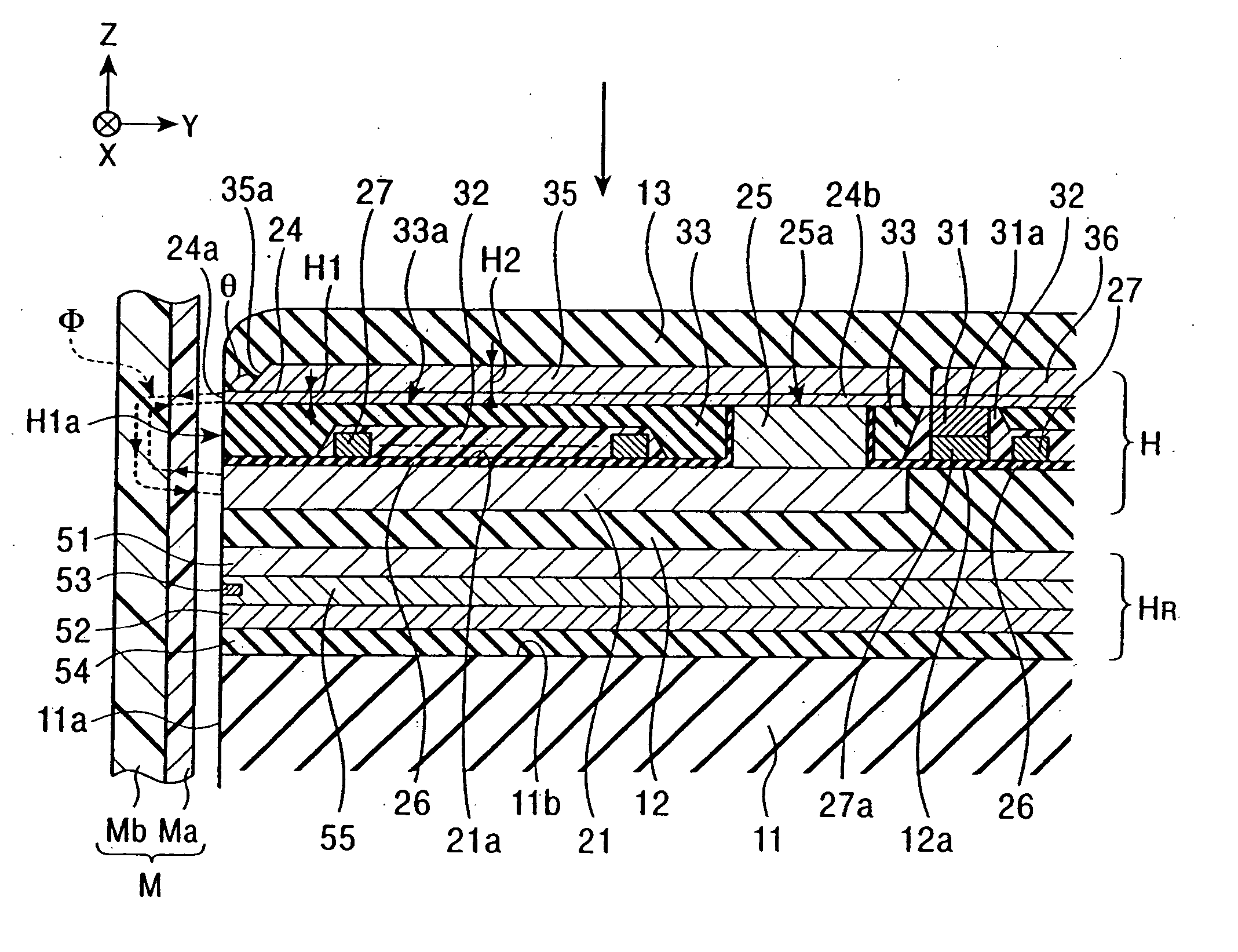
[0083]FIG. 1 is a vertical sectional view showing a structure of a perpendicular magnetic recording head according to the present invention.

[0084] In a perpendicular magnetic recording head H shown in FIG. 1, a perpendicular magnetic field is applied to a recording medium M for magnetizing a hard surface Ma of the recording medium M in the perpendicular direction.

[0085] The recording medium M is in the form of a disk, and has the hard surface Ma on its outer surface, which has high residual magnetization (remanence), and a high soft surface Mb on the inner side, which has a high magnetic permeability. The recording medium M is rotated with the disk center being the center of the rotation.

[0086] A slider 11 of the perpendicular magnetic recording head H is made of ceramic materials, such as Al2O3—TiC. The slider 11 has an opposing surface 11a positioned opposite to the recording medium M. When the recording medium M is rotated, the slider 11 floats from the surface of the recording...

second embodiment

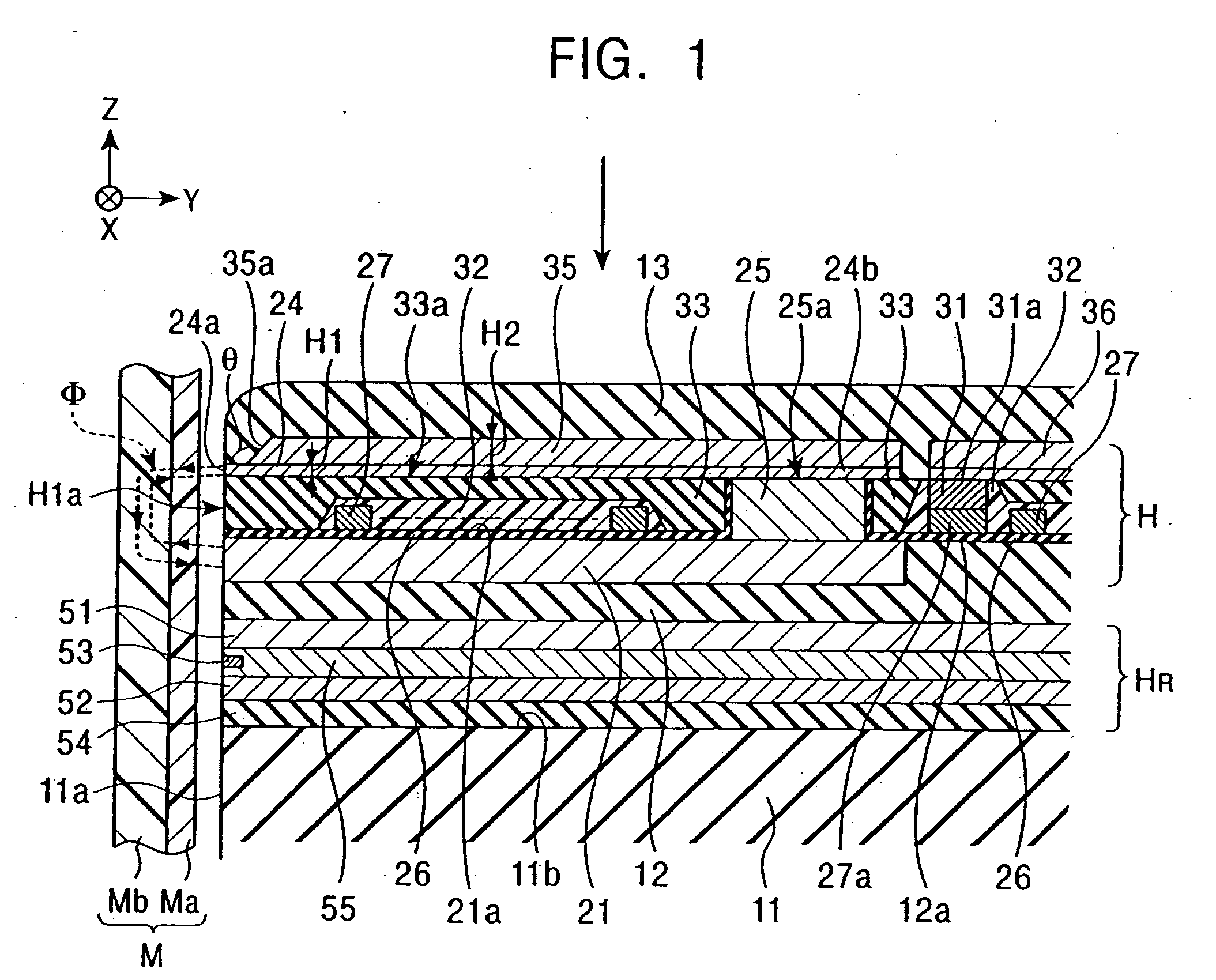
[0110]FIG. 2 is a vertical sectional view showing a structure of a perpendicular magnetic recording head according to the present invention.

[0111] The perpendicular magnetic recording head of FIG. 2 differs from that of FIG. 1 in structure of the main magnetic pole layer 24 and the yoke layer 35, although the yoke layer 35 is formed to have a film thickness H4 larger than a film thickness H3 of the main magnetic pole layer 24 as with the first embodiment. The main magnetic pole layer 24 is formed in a short length to extend from the opposing surface H1a in the height direction (Y-direction in FIG. 2). The yoke layer 35 has a front end surface 35a magnetically coupled to a rear end surface 24f of the main magnetic pole layer 24, and is formed on the insulating layer 33 to extend from the front end surface 35a rearward in the height direction. The yoke layer 35 has a base end portion 35b formed on the upper surface 25a of the connecting layer 25 for magnetic coupling between them.

[01...

third embodiment

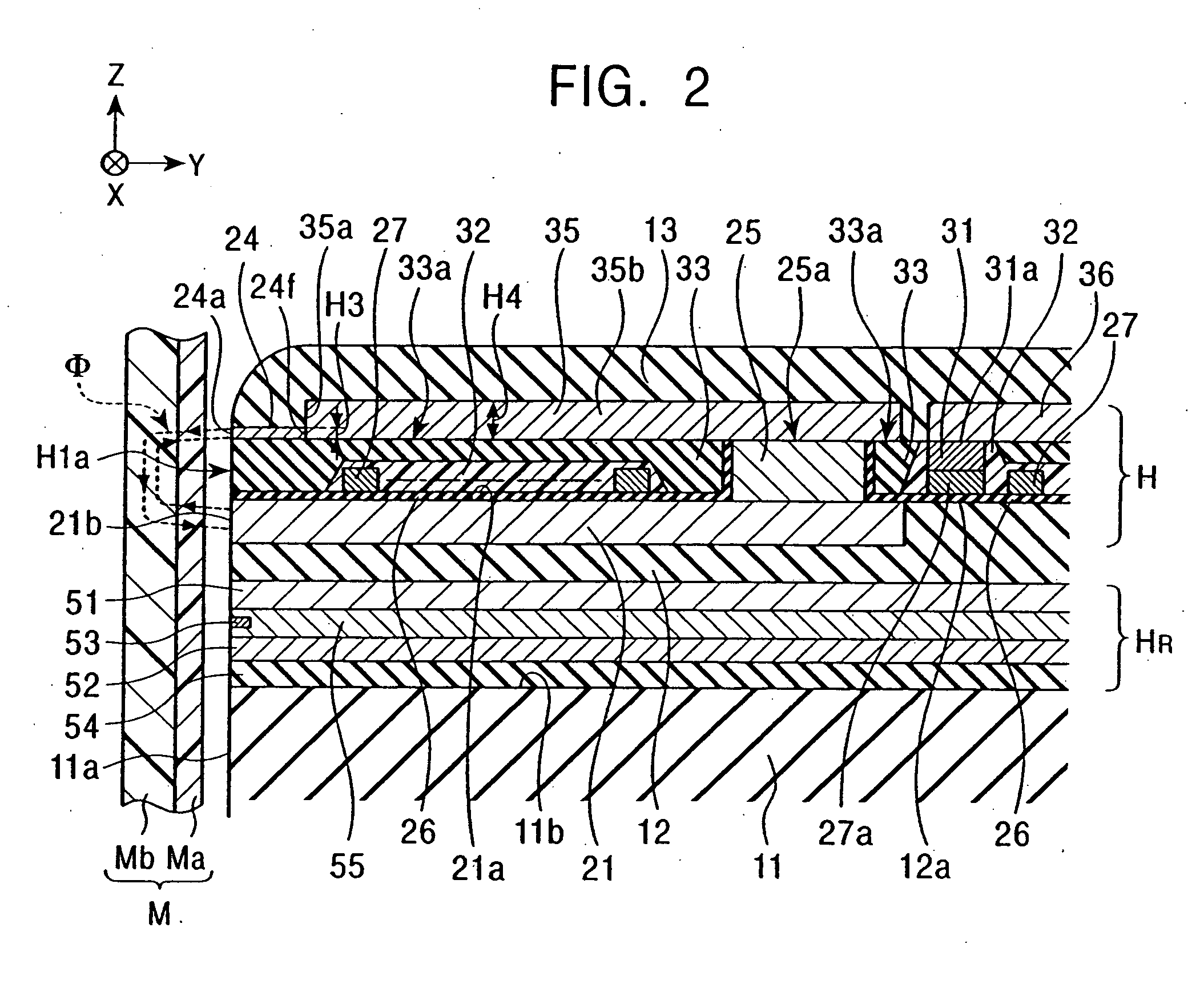
[0115]FIG. 3 is a vertical sectional view showing a structure of a perpendicular magnetic recording head according to the present invention.

[0116] The perpendicular magnetic recording head of FIG. 3 differs from that of FIG. 1 in structure of the main magnetic pole layer 24 and the yoke layer 35, although the yoke layer 35 is formed to have a film thickness H6 larger than a film thickness H5 of the main magnetic pole layer 24 as with the first embodiment. The yoke layer 35 is formed on the insulating layer 33 and has a base end portion 35b magnetically coupled to the upper surface 25a of the connecting layer 25.

[0117] Also, the yoke layer 35 has a front end surface 35a formed as a sloped or curved surface inclined toward the opposing surface H1a as it approaches an upper surface from a lower surface of the yoke layer 35. An external angle θ formed between a lower surface of the main magnetic pole layer 24, which is formed on the yoke layer 35, and the front end surface 35a of the y...


PUM

PropertyMeasurementUnit
external angleaaaaaaaaaa
track width Twaaaaaaaaaa

Abstract

A main magnetic pole layer is formed on an insulating layer flattened into a high-flatness surface, and a yoke layer having a large film thickness is formed on the main magnetic pole layer independently of the main magnetic pole. The main magnetic pole layer has a front end surface formed in a shape with a width size gradually increasing in a direction of track width as the front end surface departs farther away from an auxiliary magnetic pole layer. A perpendicular magnetic recording head can be provided which can suppress the occurrence of fringing in a recording pattern, and can form the main magnetic pole layer with high pattern accuracy, and can satisfactorily introduce a recording magnetic field to a fore end of the main magnetic pole layer.

Description

BACKGROUND OF THE INVENTION [0001] 1. Field of the Invention [0002] The present invention relates to a perpendicular magnetic recording head for recording data on a recording medium, such as a disk having a hard surface, under application of a perpendicular magnetic field. More particularly, the present invention relates to a perpendicular magnetic recording head and a method of manufacturing the head, which can suppress the occurrence of fringing in a recording pattern, can form a main magnetic pole layer with high pattern accuracy and form a yoke surface having a large film thickness, and can improve the passing efficiency of magnetic flux. [0003] 2. Description of the Related Art [0004] Conventionally, a perpendicular magnetic recording method is utilized in a device for recording magnetic data on a recording medium, such as a disk, with a high density.FIG. 38 is a sectional view showing a general structure of a perpendicular magnetic recording head for use in the known perpendic...

Claims


Application Information

Patent Timeline
Patent Type & Authority Applications(United States)
IPC IPC(8): G11B5/147G11B5/31G11B5/127G11B5/187
CPCG11B5/1278G11B5/3116G11B5/3163Y10T29/49046Y10T29/49052Y10T29/49039Y10T29/49043Y10T29/49048Y10T29/49044
Inventor TAKAHASHI, TORUYAZAWA, HISAYUKIGOCHOU, HIDEKIKOBAYASHI, KIYOSHIYAMADA, MINORUSATO, KIYOSHIWATANABE, TOSHINORI
Owner TDK CORPARATION
Why Eureka
Try Eureka