
Interlocking polymeric foam floor underlayment and process for making

a technology of interlocking polymeric foam and floor underlayment, which is applied in the field of polymeric foam structure, can solve the problems of inability to have such prior experience of floor underlayment installers, the installation of floor underlayment requires very precise positioning, and the cost and quality of the completed floor installation may not be such, so as to achieve the effect of light weight and convenient handling

Inactive Publication Date: 2006-01-05
ZWYNENBURG JAMES L +1
View PDF7 Cites 17 Cited by
  • Summary
  • Abstract
  • Description
  • Claims
  • Application Information

AI Technical Summary

Benefits of technology

[0007] It is an object of the present invention to produce a polymeric foam structure that is light in weight and easy to handle.
[0008] It is another object of the present invention to produce a polymeric foam structure that has a useful life of many years.
[0010] Lastly, it is an object of the invention to produce a resilient, non-brittle, low cost polymeric foam structure that is easy to install in the flooring application as underlayment.

Problems solved by technology

In residential applications, installers of floor underlayment may not have such prior experience.
For both cases, ease of installation of the floor underlayment is a contributing factor to the cost and quality of the completed floor installation.
A disadvantage of the simple rectangular parallelepiped floor underlayment structure is that its installation requires very precise positioning to avoid gaps between or overlaps of adjacent pieces of the underlayment.
Precise positioning of the floor underlayment increases the installation time and the overall cost of the floor.
Even small misalignment of the floor underlayment can produce unattractive seams, depressions, or bulges on the decorative flooring upper layer.
When gaps in the underlayment are present, many warranties are null and void.

Method used


Image

  • Interlocking polymeric foam floor underlayment and process for making
  • Interlocking polymeric foam floor underlayment and process for making
  • Interlocking polymeric foam floor underlayment and process for making

Examples


Embodiment Construction

[0017] In general usage the term “polymer” is accepted to mean naturally occurring or synthetic compounds consisting of large molecules made up of a linked series of many smaller identical molecules. These smaller molecules are referred to as monomers. The list of polymers in everyday use is extensive. Polymers in everyday use include polystyrene, such as in plastic beverage cups; polypropylene, such as in plastic utensils; polyethylene terephthalate, such as in carbonated beverage bottles; high density polyethylene, such as in plastic milk jugs; and linear low polyethylene, such as in plastic garbage bags.

[0018] As referred herein, the term “polymeric foam” refers to materials that are comprised of a uniform and consistent mixture of one or more solid polymers and a gaseous material wherein the two phases are arranged so that the solid phase continuously encapsulates small cells of the gas throughout the domain of the material.

[0019] As referred herein, the term “polymeric foam s...


PUM

PropertyMeasurementUnit
densityaaaaaaaaaa
densityaaaaaaaaaa
densityaaaaaaaaaa

Abstract

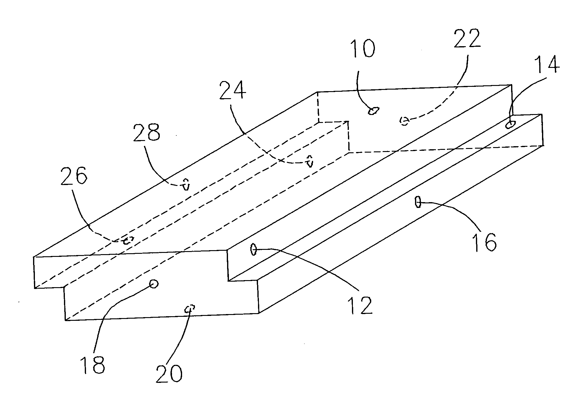
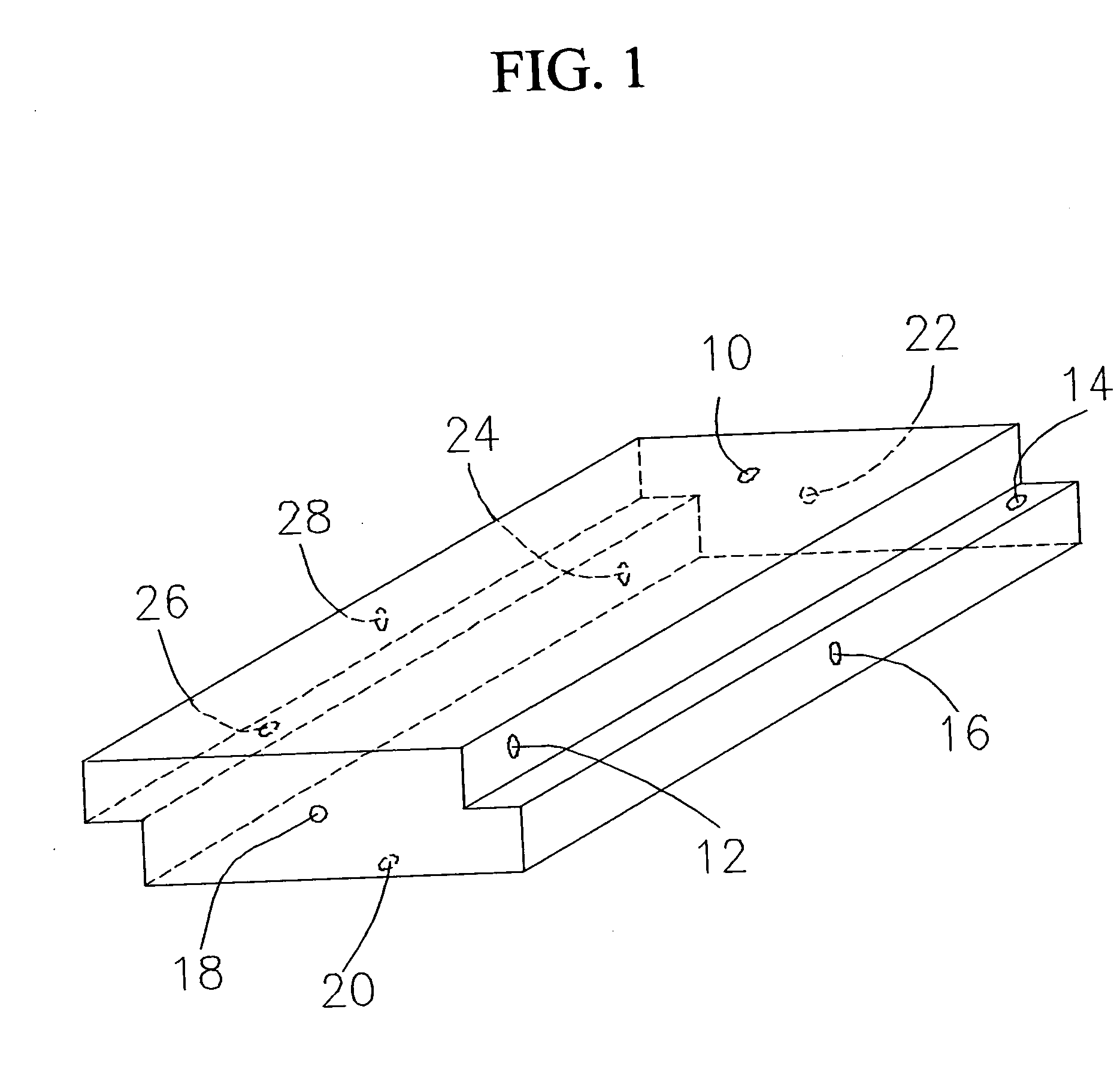
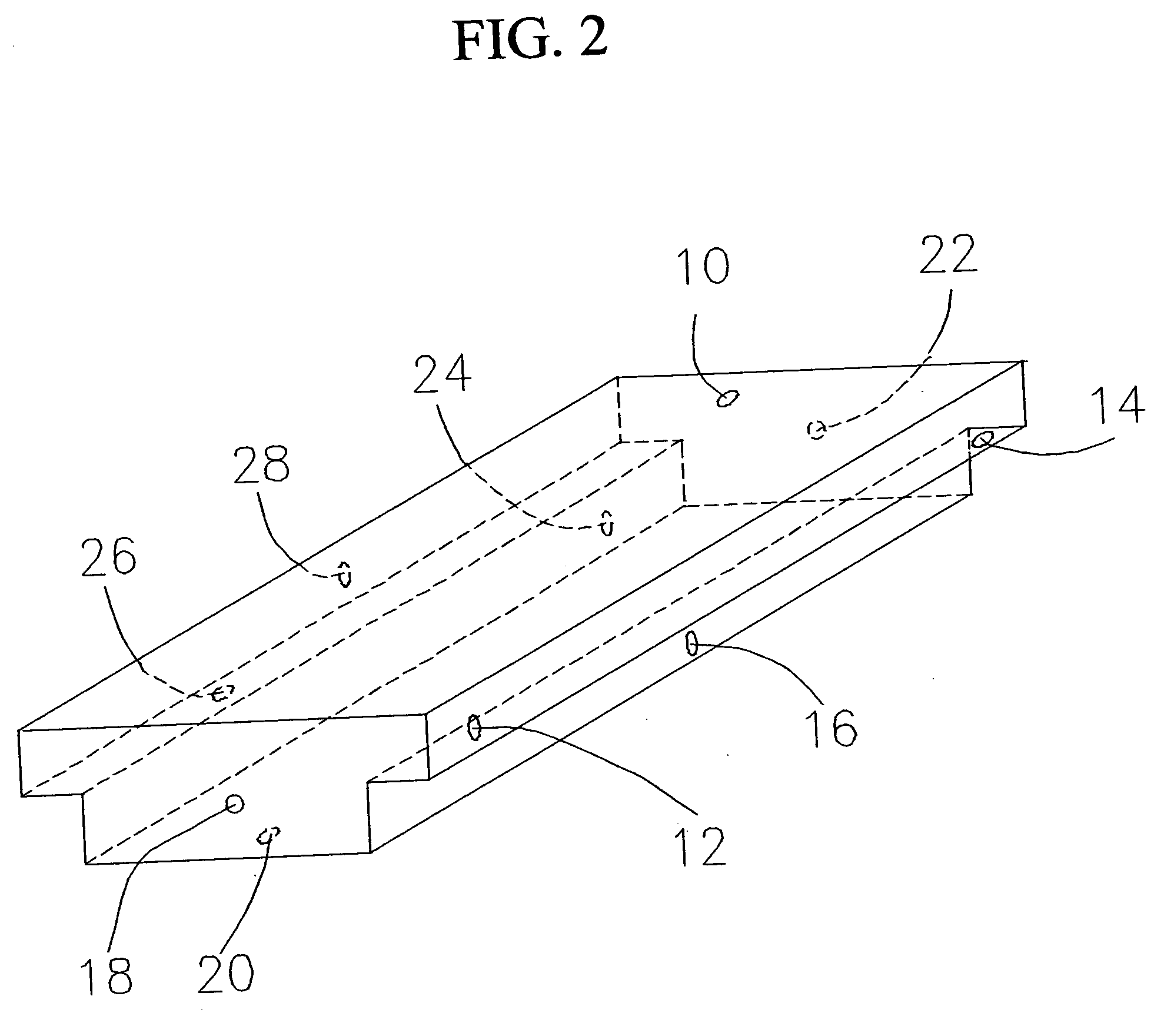
A polymeric foam structure for use as a supporting pad for floor surface layers made from laminated flooring, carpet, tile, or other functional materials. The polymeric foam structure comprises a continuous band having increased density and consistent width along each side of the polymeric foam structure. The bands may have a flat surface or they may be optionally equipped with a plurality of peaks and valleys continuing along the band in an alternating grid pattern. The bands may be oriented so that the thickness step occurs from the same surface or that the thickness step occurs on opposite surfaces. The bands of increased foam density on the polymeric foam structure may be produced by a batch thermoforming process or continuous process comprising an apparatus having heated cylindrical rollers.

Description

BACKGROUND OF THE INVENTION [0001] The present invention is directed to a polymeric foam structure suitable for installation on floors as a supporting pad for the floor surface layer made from laminate flooring, carpet, tile, or other functional material. [0002] Modern floors for commercial and residential buildings generally comprise three layers. The lower layer is typically a permanent sub-floor with a raw, unfinished surface. This sub-floor may be made of concrete, wood, or other solid material. The center layer is typically a padding material called an “underlayment”. Underlayment in common use has been composed of a variety of flexible, resilient materials, such as cork, polymeric foams, felt, and rubber. The top flooring layer typically has a decorative finished exterior surface. The top layer may be laminate flooring, carpet, asphalt tiles, linoleum, or other solid materials. Depending upon the needs and desires of the trustee of the building, the underlayment and the decora...

Claims


Application Information

Patent Timeline
Patent Type & Authority Applications(United States)
IPC IPC(8): B32B3/26
CPCB32B5/18E04F15/02Y10T428/24479Y10T428/24496Y10T428/24488E04F15/187E04F15/203
Inventor ZWYNENBURG, JAMES L.WILKES, GARY R.
Owner ZWYNENBURG JAMES L
Learn More