Suture locking and cutting devices and methods

a technology of suture locking and cutting device, which is applied in the field of endoscopic suturing device and method, can solve the problems of multiple instruments, long patient recovery period, and adds complexity to medical procedures, and achieves the effect of simplifying medical procedures and avoiding more invasive laparoscopic procedures

Inactive Publication Date: 2006-01-05
ETHICON ENDO SURGERY INC
View PDF23 Cites 416 Cited by
  • Summary
  • Abstract
  • Description
  • Claims
  • Application Information

AI Technical Summary

Benefits of technology

[0008] Applicants recognize the desirability of providing improved methods of performing a totally transoral surgical procedure, such as a posterior gastropexy procedure, and thereby avoid more-invasive laparoscopic procedures. Applicants also recognize the desirability of providing a single mechanism for automatically locking and cutting a suture and thereby simplifying medical procedures, such as, but not limited to, a posterior gastropexy procedure; and the desirability of providing suture locking and cutting mechanisms that are small enough to pass through the working channel of various endoscopic and ultrasound devices.
[0009] Certain embodiments of the present invention are directed to providing improved methods of performing a totally transoral surgical procedure, such as a posterior gastropexy procedure, and thereby avoiding more-invasive laparoscopic procedures. One embodiment of the present invention provides a device and method that allows a physician in a medical procedure to automatically lock and cut a suture in one motion and without the need for additional cutting instrumentation, rather than perform separate locking and cutting actions.

Problems solved by technology

Such procedures are invasive, as laparoscopy requires that small access incision(s) be made in the body of the patient, through which a laparoscope and other surgical enabling tools are provided, while open surgical techniques are traditionally invasive and can have complications and cause long patient recovery periods.
This may result in multiple passes of instrumentation back and forth through the working channel of the endoscope.
Additionally, the locking mechanism described in the publication is too large to pass through the working channel of an endoscope and, thus, it must be inserted into the patient separately from the endoscope, which again adds complexity to the medical procedure.

Method used


Image

  • Suture locking and cutting devices and methods
  • Suture locking and cutting devices and methods
  • Suture locking and cutting devices and methods

Examples


first embodiment

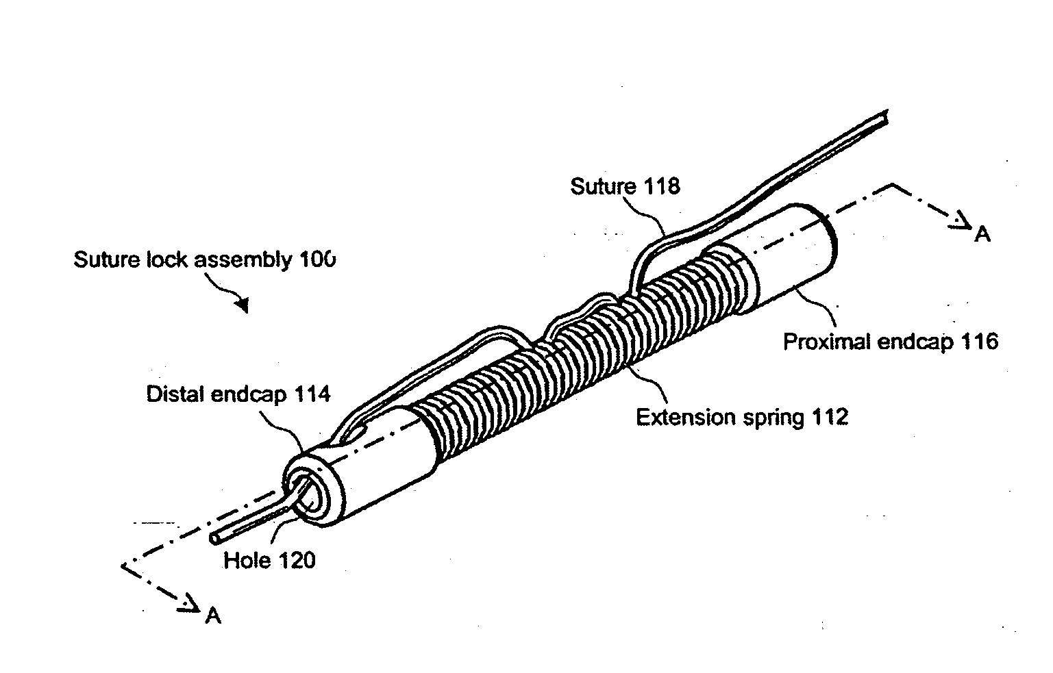
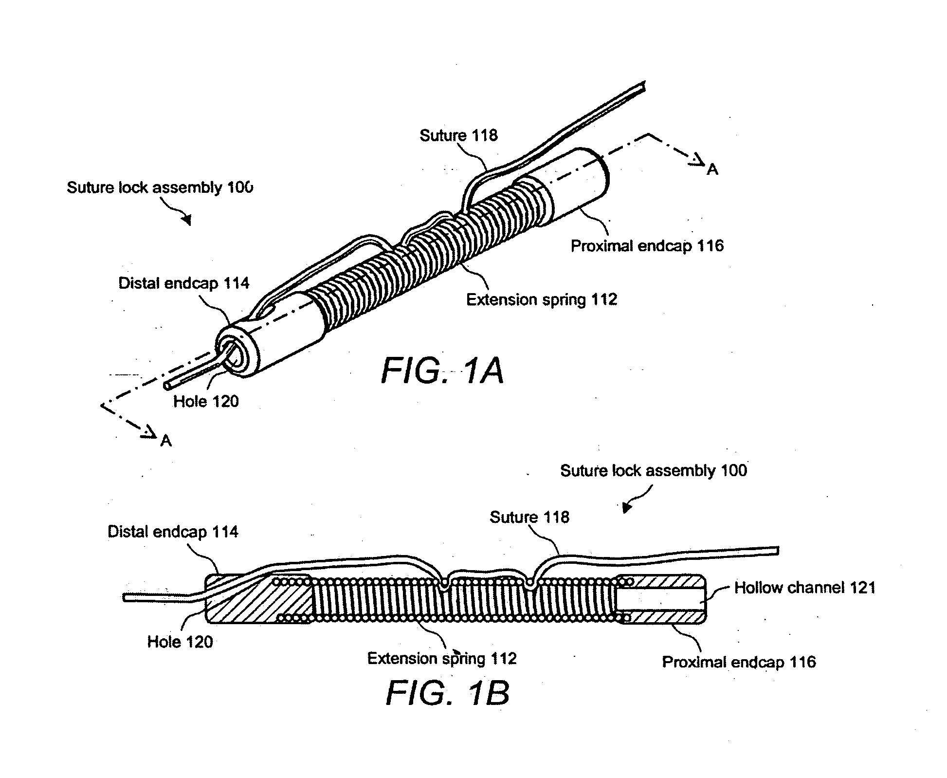
[0027]FIG. 1A illustrates a perspective view of a suture lock assembly 100 in accordance with the invention. Suture lock assembly 100 includes an extension spring 112 arranged between a distal endcap 114 and a proximal endcap 116.

[0028] Extension spring 112 is formed of any nontoxic, noncorrosive metal, such as stainless steel, and distal endcap 114 and proximal endcap 116 are formed of, for example, molded plastic or stainless steel. Also shown in FIG. 1 is a suture 118 threaded first through a hole 120 in distal endcap 114 and then through multiple coils of extension spring 112, wherein suture 118 is clamped because of the pressure of the coils and the tortuous path within the coils. Suture lock assembly 100 is not limited to a single suture 118 installed therein; a plurality of sutures 118 may be engaged within a single suture lock assembly 100.

[0029]FIG. 1B illustrates a cross-sectional view of suture lock assembly 100 taken along line AA of FIG. 1A. This view shows that proxim...

second embodiment

[0057]FIG. 8 illustrates a perspective view of a suture lock assembly 800 in accordance with the invention. Suture lock assembly 800 includes a cylindrical-shaped lock body 810 that further includes a plurality of suture channels 812 that run therethrough, and which have an associated plurality of locking holes 814 arranged on the outer surface of lock body 810. Suture lock assembly 800 further includes a lock sleeve 816 that further includes a cavity 818 (shown in FIGS. 9 and 10) within which lock body 810 is inserted. Lock body 810 further includes a first groove 824 and a second groove 826, which are detents formed around the outer perimeter of lock body 810. Lock sleeve 816 further includes a first locking ring 820 and a second locking ring 822, which are raised regions protruding from the inside perimeter of cavity 818 that are sized to lock within the detents formed by first groove 824 and second groove 826 of lock body 810.

[0058] Also shown in FIG. 8 is suture 118, which is a...


PUM


Abstract

Suture holding devices and methods are disclosed, including devices and methods useful in performing a transoral surgical procedure, such as a posterior gastropexy procedure. A device is disclosed which can be used by a physician in a medical procedure to automatically lock and cut a suture in one motion and without the need for additional cutting instrumentation, rather than perform separate locking and cutting actions.

Description

CROSS-REFERENCE TO RELATED APPLICATIONS [0001] This application claims priority to and incorporates by reference the following applications: U.S. Provisional Application 60 / 571,117 filed May 14, 2004; U.S. provisional Application 60 / 571,119 filed May 14, 2004; and U.S. Provisional Application 60 / 571,000 filed May 14, 2004.FIELD OF THE INVENTION [0002] This invention relates to endoscopic suturing devices and methods, including devices and methods which may pass through or be employed in connection with the working channel of various endoscopic and ultrasound devices. BACKGROUND [0003] Application of sutures in the gastrointestinal tract is required for several different types of medical procedures, for example, for transoral endoscopic valvuloplasty for gastroesophageal reflux disease (GERD), gastroplasty, fundoplication, anterior gastropexy, posterior gastropexy, suturing esophageal perforations, or closure of the esophageal side of the tracheo-esophageal fistula. Traditionally, th...

Claims


Application Information

Patent Timeline
Patent Type & Authority Applications(United States)
IPC IPC(8): A61B17/04
CPCA61B17/0401A61B2017/06052A61B17/0469A61B17/0487A61B17/06166A61B2017/0409A61B2017/0417A61B2017/0445A61B2017/045A61B2017/0451A61B2017/0454A61B2017/0458A61B2017/0464A61B2017/0488A61B2017/0496A61B17/0467
Inventor NOBIS, RUDOLPH H.VAKHARIA, OMAR J.FAUX, JOHN A.SWAIN, CHRISTOPHER PAULMOSSE, CHARLES ALEXANDER
Owner ETHICON ENDO SURGERY INC
Why Eureka
Try Eureka