Shift lever lock device for vehicular automatic transmission

a technology of automatic transmission and shift lever, which is applied in the direction of mechanical control devices, process and machine control, instruments, etc., can solve the problems of preventing the device from providing a space-saving structure and unable to provide a smooth and quick rotary movement with the follower, so as to reduce the load applied and save the cost of materials

Inactive Publication Date: 2006-01-12
HAMANAKODENSO
View PDF3 Cites 2 Cited by
  • Summary
  • Abstract
  • Description
  • Claims
  • Application Information

AI Technical Summary

Benefits of technology

[0020] The first movable core and the second movable core stick together from the original position, thus obviating the first movable core from hitting the second movable core to eliminate an operational noise which would otherwise be produced as a hitting noise.
[0031] Even if a larger downward load is applied to the upper leg portion of the lock plate at the time of locking the shift lever, it is possible for the casing to bear the downward load imposed on the outer circumferential portion of the casing with the prong portion slid into the notched portion. This mitigates the load applied to the lower cylindrical portion, thus preventing the lower cylindrical portion from unfavorably deformed so as to maintain a smooth rotational movement of the lock plate. As a result, it comes possible to cope with the downward load with a thickness-reduced and lightweight lock plate so as to save the cost used for materials.

Problems solved by technology

However, the magnet metal is mounted on the middle of the follower, thus making the follower lengthened in its axial direction so as to occupy a larger space, which deters the device from providing a space-saving structure with it.
The magnet metal adds its weight to the follower so as to make it difficult to provide a smooth and quick rotary movement with the follower when the follower rotationally moves in the predetermined direction.
The repetitive deformation subjected to electric lead wires may give the lead wires fatigues resulting them in disconnection at the worst case.

Method used


Image

  • Shift lever lock device for vehicular automatic transmission
  • Shift lever lock device for vehicular automatic transmission
  • Shift lever lock device for vehicular automatic transmission

Examples


first embodiment

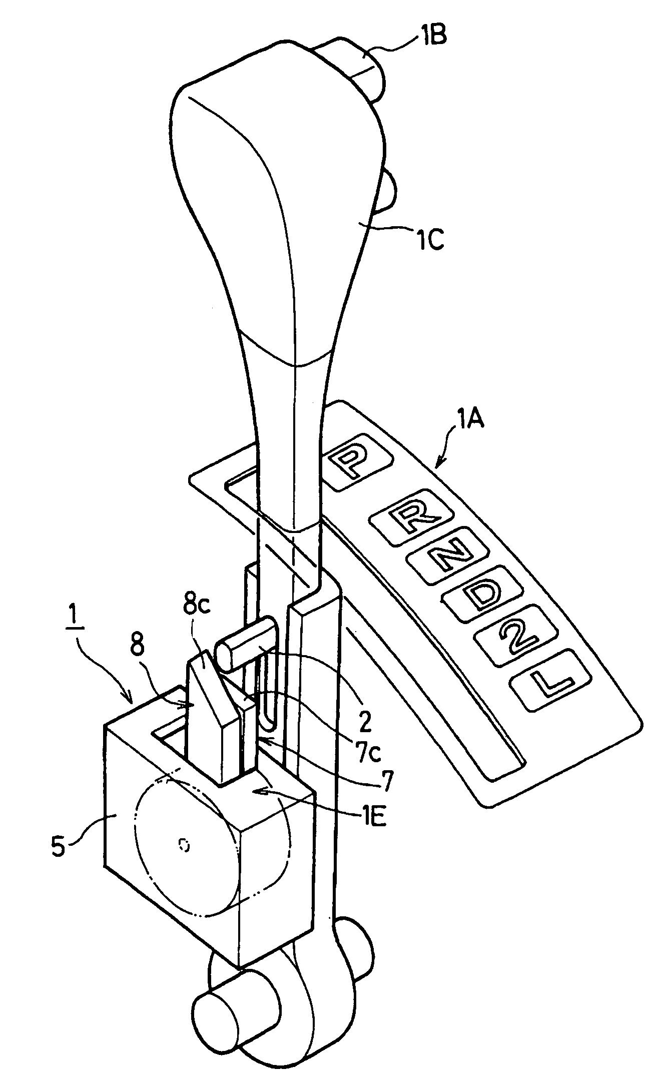
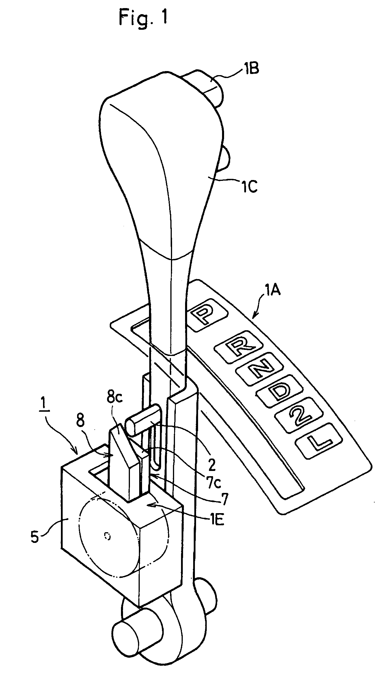
[0043] Referring to FIGS. 1 and 6 which show a shift lever lock device 1 for vehicular automatic transmission according to the invention, an operational shift portion 1A is provided in the vehicular automatic transmission as shown in FIG. 1. In the shift lever lock device 1, a lock mechanism portion 1E is provided within a casing 5. The shift lever lock device 1 may be of any type regardless of whether it is of straight-gate type or column-gate type one.

[0044] The operational shift portion 1A has a shift lever 1C, an upper end of which has a select button 1B to be operated toward P-range position (parking position), R-range position, N-range position, D-range position and L-range position.

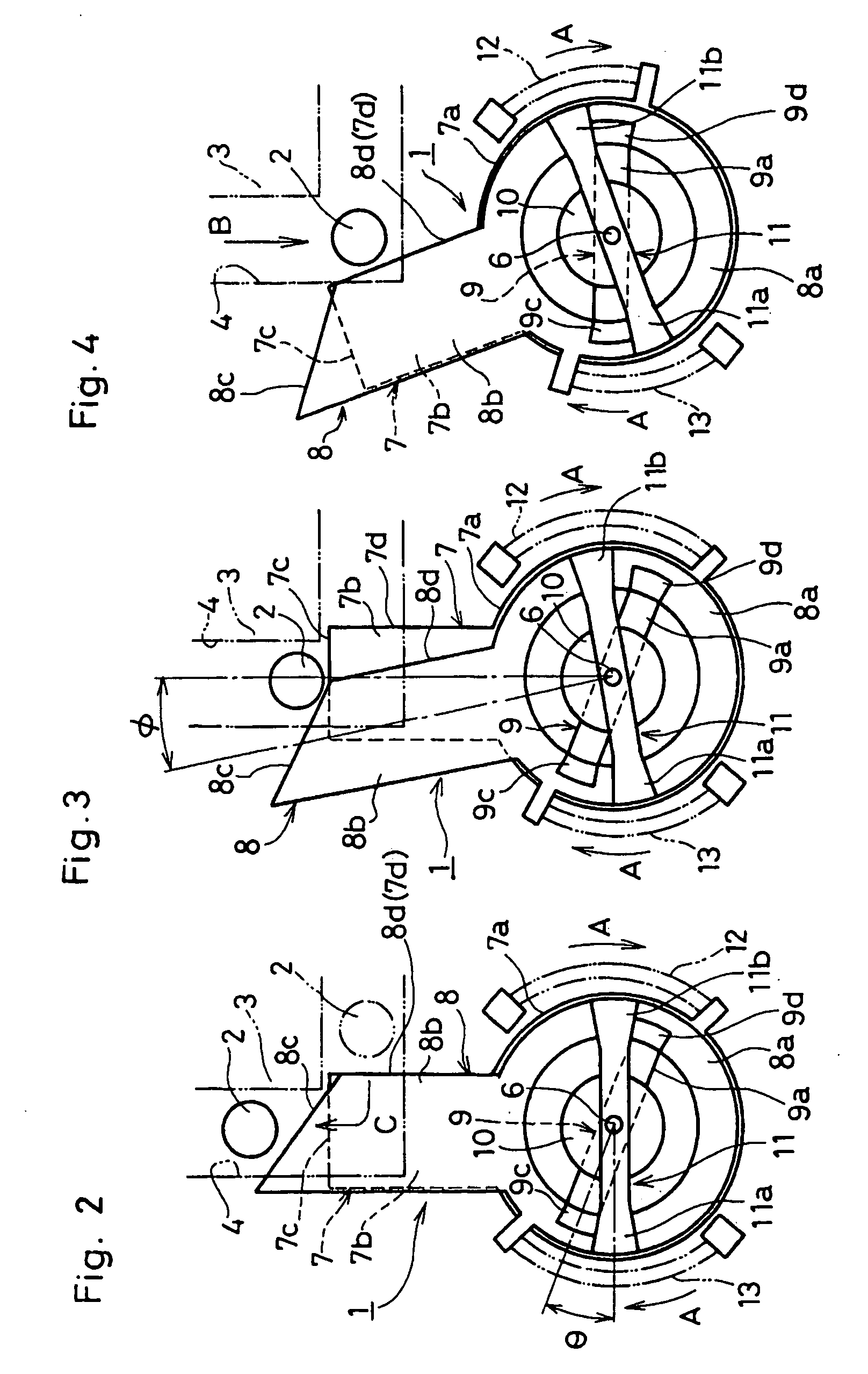
[0045] As shown in FIG. 2, the shift lever 1C is in P-range position, and a detent pin 2 is adapted to slide along a detent groove 4 provided on a detent plate 3 which is omitted in FIG. 1. The detent pin 2 axially moves along the shaft lever 1C in association with the select button 1B being opera...

second embodiment

[0071]FIG. 7 shows the invention in which the first movable core 11 omits a part of the support portion 9a with the second movable core 11 substantially halved in length. This contributes to saving the materials to realize the lightweight movable cores 9, 11.

third embodiment

[0072]FIGS. 8 through 15 show the invention in which the lock plate 7 and the link plate 8 locate their lower cylindrical portions 7a, 8a in a casing 15 (see FIGS. 8, 9) with the upper leg portions 7b, 8b exposed outside the casing 15 as shown in FIG. 10.

[0073] In more tangible terms, the lock plate 7 fits the lower cylindrical portion 7a to rotatably slide into an annular inner wall 15a defined on a left half of the casing 15. The link plate 8 fits the lower cylindrical portion 8a to rotatably slide into an annular inner wall 15b defined on a right half of the casing 15.

[0074] Between the casing 15 and the lock plate 7, a first torsion helical spring 17 is provided as a first urging member. Between the casing 15 and the link plate 8, a second torsion helical spring 18 is provided as a second urging member. The annular inner wall 15b is designed to be diametrically larger than the annular inner wall 15a so as to define a stepped border portion 16 therebetween. The stepped border po...


PUM


Abstract

In association with a solenoidal coil 10 being energized to unlock a shift lever, a first movable core 9 and a second movable core 11 magnetically stick together so as to rotationally move in unison from an original position in which the first movable core 9 engages with the second movable core 11. Because the first movable core 9 and the second movable core 11 stick together before unlocking the shift lever, it is possible to avoid the first movable core 9 from hitting the second movable core 11 so as to eliminate an operational noise which would otherwise be produced by hitting the first movable core 9 against the second movable core 11. A lock plate 7 and a link plate 8 are rotatably provided around a rotational center 6 in relative to the solenoidal coil 10. This prevents the lock plate 7 and the link plate 8 from moving rotationally in unison with the solenoidal coil 10, thus enabling the lock plate 7 and the link plate 8 to a smooth and quick rotational movement.

Description

BACKGROUND OF THE INVENTION [0001] 1. Field of the Invention [0002] The invention relates to a shift lever lock device for vehicular automatic transmission in which a solenoidal coil is energized to produce a magnetic attraction upon unlocking a shift lever. [0003] 2. Description of Prior Art [0004] In a shift lever lock device which is mounted on a vehicular automatic transmission, a locking mechanism is provided to effectuate a reverse shift lock and a parking shift lock to insure a safety on navigation by utilizing an electronic solenoid. The reverse shift lock prevents the shift lever from inadvertently moving toward R-range position so as to eliminate a reverse shift shock when the navigating the vehicle at the speed exceeding a predetermined limit. [0005] The parking shift lock prevents the shift lever from inadvertently moving toward D-range position from P-range position once a vehicle is parked with the shift lever located in P-range position. [0006] Upon actuating an ignit...

Claims


Application Information

Patent Timeline
Patent Type & Authority Applications(United States)
IPC IPC(8): F16H59/00B60K20/02B60K20/00F16H59/10F16H61/22
CPCF16H59/10F16H61/22Y10T74/2011Y10T74/20098Y10T74/20104Y10T74/20085
Inventor INOGUCHI, TETSUNORISUZUKI, MASANORI
Owner HAMANAKODENSO
Why Eureka
Try Eureka