Cooling module

Inactive Publication Date: 2006-01-12
FUJITSU LTD
View PDF15 Cites 22 Cited by
  • Summary
  • Abstract
  • Description
  • Claims
  • Application Information

AI Technical Summary

Benefits of technology

[0023] The cooling module enables airflow from the ventilation fan to flow along the wall of the endoergic chamber in the first passage. The cooling module also enables airflow from the ventilation fan to flow along the wall of the radiative cham

Problems solved by technology

Unless the radiation fins are formed sufficiently higher, a efficient radiation of heat cannot be achi

Method used


Image

  • Cooling module
  • Cooling module
  • Cooling module

Examples


Example

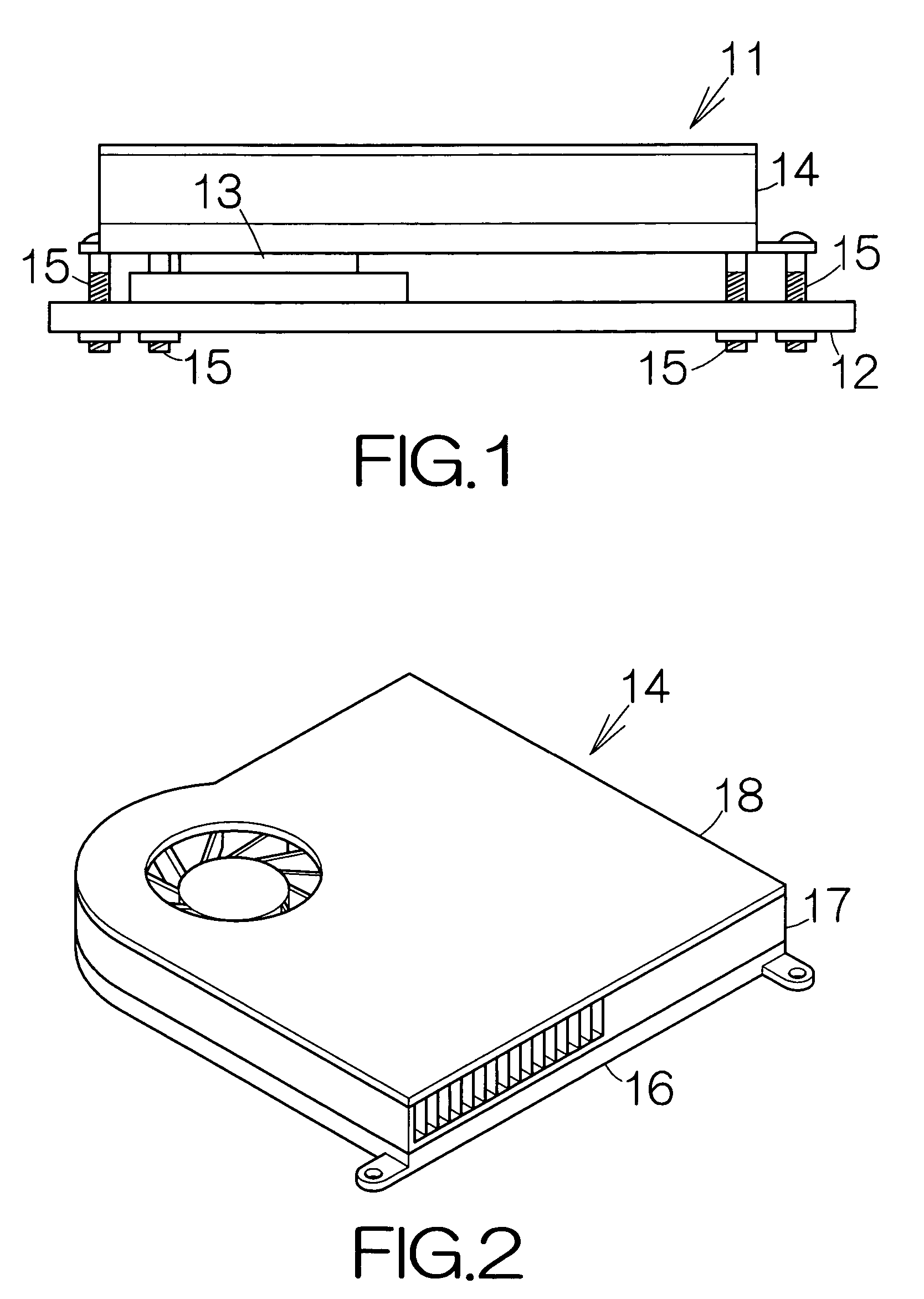
[0030]FIG. 1 illustrates a schematic view of a printed circuit board unit 11. The printed circuit board unit 11 includes a printed circuit board 12 and a central processing unit (CPU) 13 mounted on the printed circuit board 12, for example. The CPU 13 is allowed to operate based on software programs temporarily stored in a memory, not shown, for example. The CPU 13 generates heat during the operation. A cooling module 14 is placed on the CPU 13. The cooling module 14 serves to cool the CPU 13. Screws 15 may be employed to couple the cooling module 14 to the printed circuit board 12.

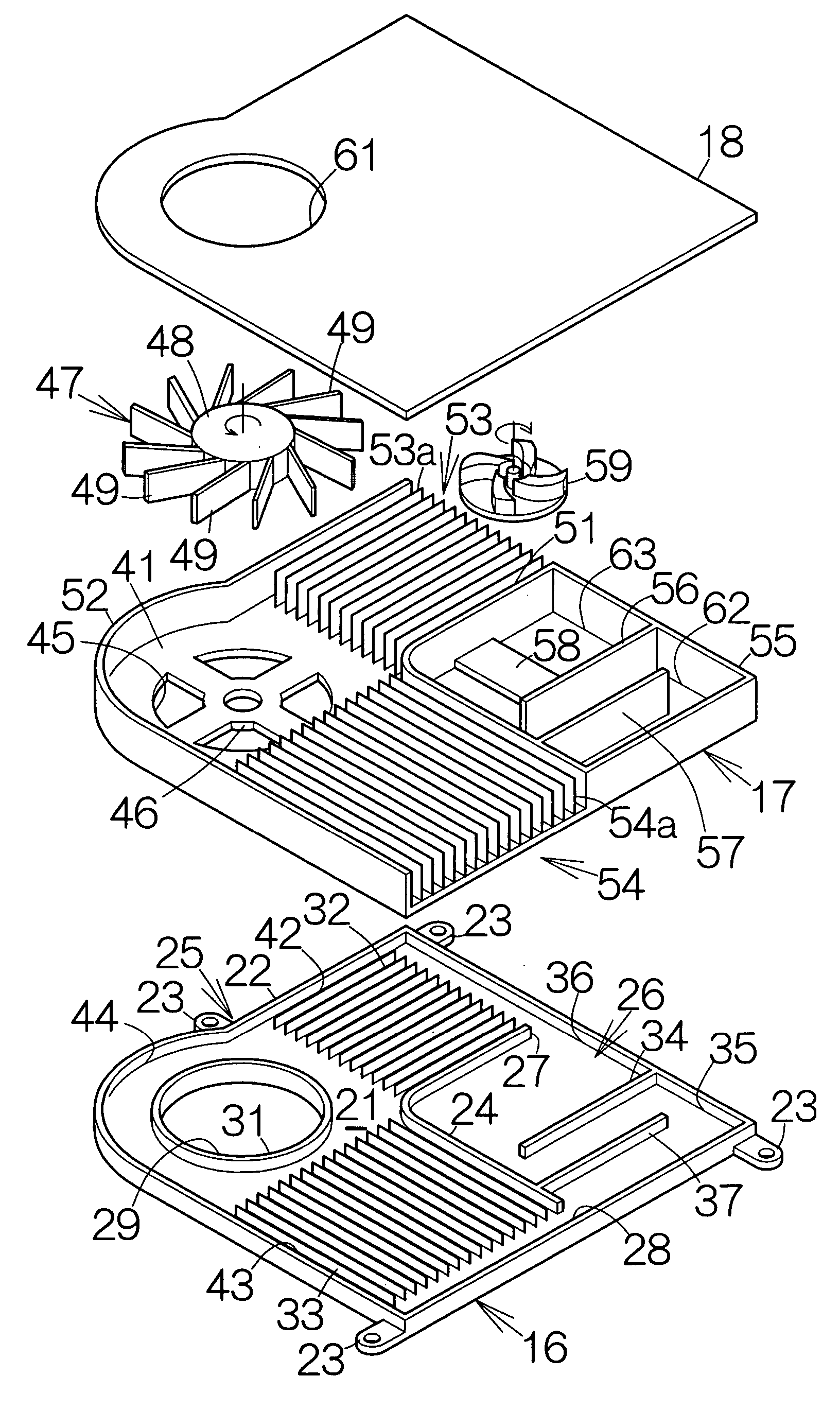
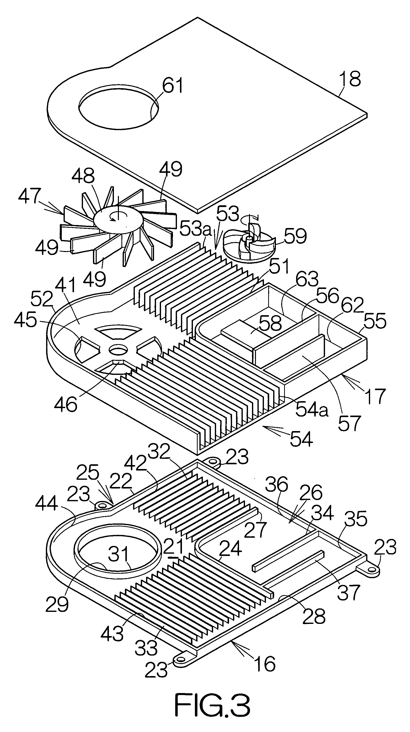
[0031] As shown in FIG. 2, the cooling module 14 includes a first housing 16. A second housing 17 is placed on the first housing 16. A cover 18 is placed on the second housing 17.

[0032] As shown in FIG. 3, the first housing 16 includes a lower thermal conductive plate 21. A peripheral wall 22 is formed along the outer periphery of the lower thermal conductive plate 21. The peripheral wall 22 stands from...


PUM


Abstract

A cooling module includes a thermal conductive member. An endoergic chamber, a radiative chamber and a circulation pump chamber are defined along the thermal conductive member. The thermal conductive member contacts a heat generating object outside the endoergic chamber. The thermal energy is transferred to the coolant in the endoergic chamber. The coolant then flows into the radiative chamber. The thermal energy of the coolant is taken away in the radiative chamber. The thermal energy is radiated from the outer wall surface of the radiative chamber. This cooling cycle is repeated so that an efficient cooling operation can be realized in the cooling module. Arrangement of the endoergic, radiative and circulation pump chambers along the thermal conductive member leads to a minimized height of the cooling module.

Description

BACKGROUND OF THE INVENTION [0001] 1. Field of the Invention [0002] The present invention relates to a cooling module comprising an endoergic chamber designed to transfer thermal energy to a coolant, and a radiative chamber connected to the endoergic chamber so as to absorb the thermal energy from the coolant. [0003] 2. Description of the Prior Art [0004] A cooling module often includes radiation fins. The cooling module of the type usually includes a thermal conductive plate contacting a heat generating object such as a large-scale integrated circuit (LSI) chip, as disclosed in Japanese Patent Application Publication No. 8-32263. The radiation fins are fixed to the thermal conductive plate. The thermal energy of the LSI chip is transferred to the coolant through the thermal conductive plate. The coolant flows within the radiation fins. The thermal energy of the LSI chip is in this manner transferred to the radiation fins. The thermal energy of the coolant is then radiated into the ...

Claims


Application Information

Patent Timeline
IPC IPC(8): H05K7/20
CPCH01L23/467H01L23/473H01L2924/0002H01L2924/00
Inventor WEI, JIESUZUKI, MASAHIRO
Owner FUJITSU LTD
Why Eureka
Try Eureka