Phase change memory with extra-small resistors

a phase change memory and resistor technology, applied in the field of electronic memories, can solve the problems of limited efforts of most of the time, and achieve the effects of high density memory, small resistor or heater, and good scalability

Inactive Publication Date: 2006-01-12
JIANG HAI
View PDF4 Cites 160 Cited by
  • Summary
  • Abstract
  • Description
  • Claims
  • Application Information

AI Technical Summary

Benefits of technology

[0011] An object of the present invention is to provide a new phase change memory structure with extremely small resistor or heater. It is also an object of the present invention to pro

Problems solved by technology

However most of these efforts are limited either by the resolution of the photolithography p

Method used


Image

  • Phase change memory with extra-small resistors
  • Phase change memory with extra-small resistors
  • Phase change memory with extra-small resistors

Examples


Embodiment Construction

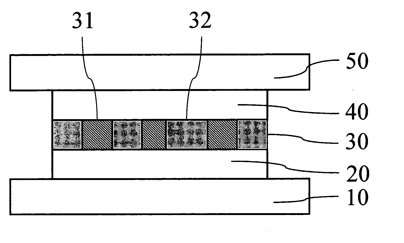
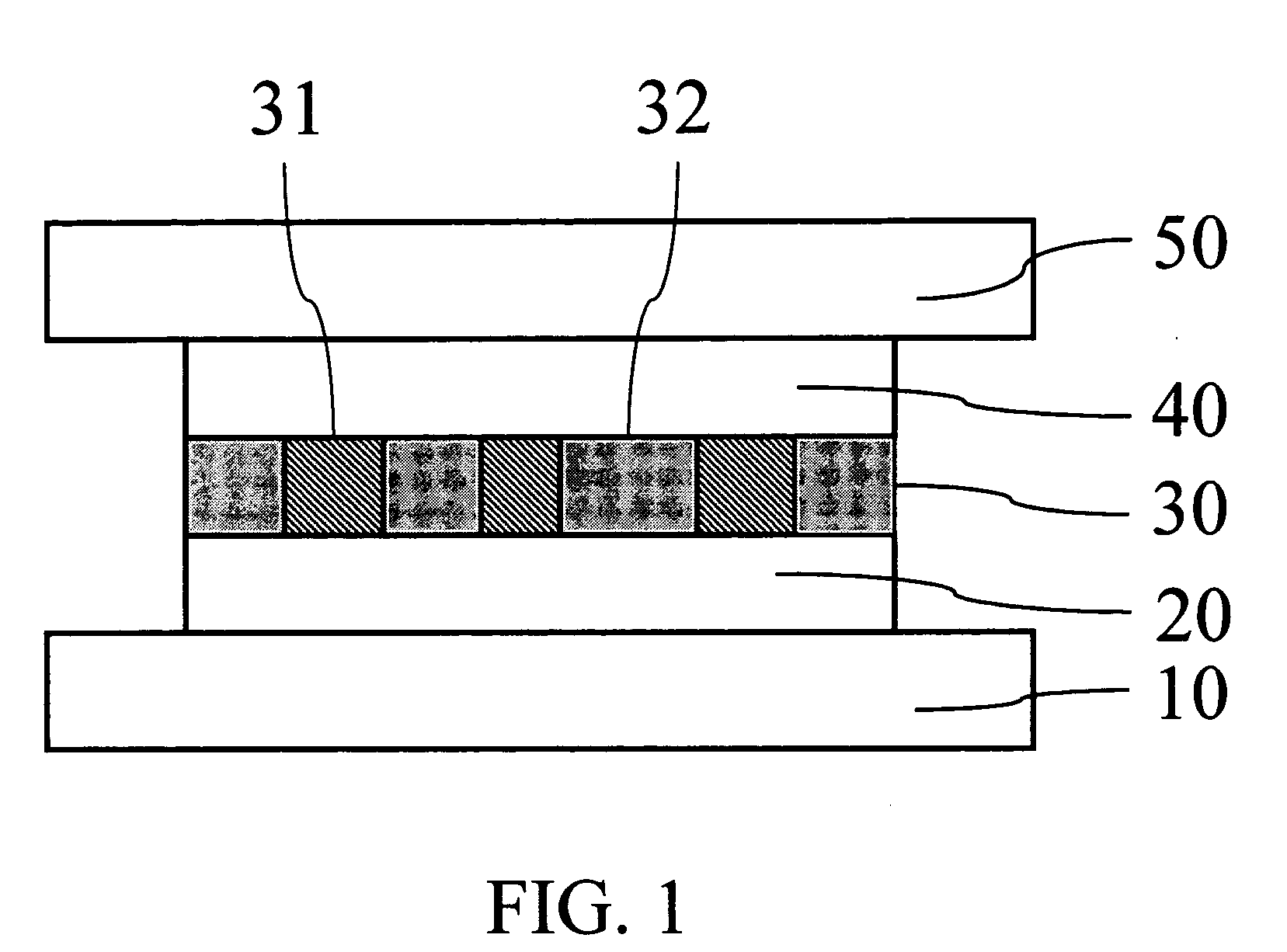
[0017]FIG. 1 is a cross sectional view illustrating a memory cell structure with multiple resistors. The memory cell comprises of 3 layers: electrode layers 20 and 40, resistor layer 30. The resistor layer 30 is a layer where some resistors 31 with size of about 1 nm to several tens nm (1 nm=10−9 m) embedded uniformly in a high resistance matrix 32. The electrode layers 20 and 40 are made of conductive material. The whole memory cell is located between the address lines 10 and 50.

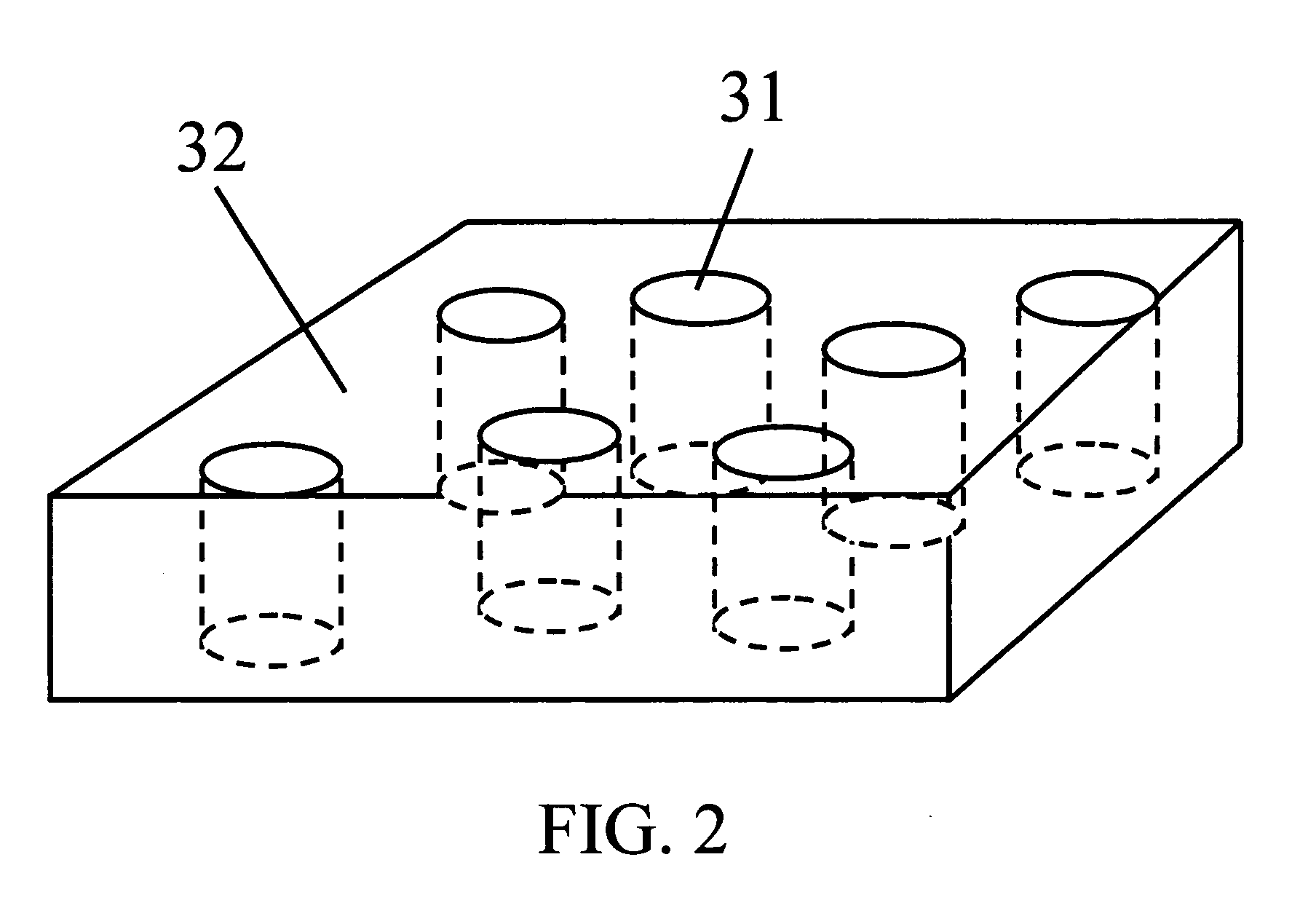
[0018]FIG. 2 shows a simplified and enlarged perspective view illustrating the structure of resistor layer. The size of resistor 31 is defined herein as the diameter of the resistor, or its “characteristic dimension” which is equivalent to the diameter where the resistors are not cylindrically shaped. The resistor is made of phase change material and has much smaller resisitivity than the matrix material so that current mainly flows through the resistors 31. The resistors 31 contact with upper electrode 40...


PUM


Abstract

A phase change memory cell comprises of multiple resistors. In one design, the resistor layer is a layer with a plurality of resistors embedded in an insulator layer which is sandwiched between the electrodes. In the other design, a combination of a heater layer with a plurality of heaters and a layer of phase change material constitutes the resistor sandwiched a pair of electrodes. The resistor or heater can be easily made in nano-size.

Description

CROSS-REFERENCE TO RELATED APPLICATIONS [0001] This is a continuation of application Ser. No. 10 / 453 / 325, filed on Jun. 03, 2003, now abandoned.FEDERALLY SPONSORED RESEARCH [0002] none FIELD OF THE INVENTION [0003] This invention relates generally to electronic memories that use phase change materials, and particularly to the structure, materials, and fabrication of the memory cell. THE BACKGROUND OF THE INVENTION [0004] The phase change memory is a kind of non-volatile memory that uses phase change material to store the information. Typically, a phase change memory cell consists of a resistor located between two electrodes. The resistor is made of phase change material and can be switched in different resistance values corresponding to different states of the phase change material. The states may be called the amorphous or crystalline states. The amorphous state generally exhibits higher resistivity than the crystalline state. The state of phase change material is changed by the re...

Claims


Application Information

Patent Timeline
IPC IPC(8): H01L23/62
CPCG11C2213/52H01L45/06H01L45/144H01L45/1246H01L45/126H01L45/1233H10N70/828H10N70/231H10N70/8413H10N70/826H10N70/8828
Inventor JIANG, HAI
Owner JIANG HAI
Why Eureka
Try Eureka