Control apparatus for use with driving device of vehicle

a control apparatus and driving device technology, applied in the direction of brake systems, instruments, gearing, etc., can solve the problems of no power transmission device that has the respective advantages, and the driving device as a whole cannot help occupying a large space, so as to achieve high fuel consumption rate, improve fuel consumption rate, and achieve high transmission efficiency

Inactive Publication Date: 2006-01-12
TOYOTA JIDOSHA KK
View PDF2 Cites 29 Cited by
  • Summary
  • Abstract
  • Description
  • Claims
  • Application Information

AI Technical Summary

Benefits of technology

[0017] In the control apparatus in accordance with the second feature of the present invention, the coupling device selectively switches the differential device of the driving device of the vehicle, to the differential state thereof in which the differential device exhibits the differential function, or to the locked state thereof in which the differential device does not exhibit the differential function. Therefore, the driving device can enjoy the two advantages, i.e., the fuel consumption rate improving effect of the transmission whose speed ratio is electrically changeable and the high transmission efficiency of the gear type transmission that mechanically transmits the driving power. For example, in a cruising or service engine output range in which the vehicle runs at a low or intermediate speed or at a low or intermediate output, the differential device is switched to the differential state thereof so that a high fuel consumption rate of the vehicle is obtained; and, when the vehicle runs at a high speed, the differential device is switched to the locked state thereof in which the output of the engine is transmitted to the drive wheels exclusively via the mechanical, power transmission path and accordingly the conversion loss between the driving power and the electric energy that would be produced when the differential device is operated as the transmission whose speed ratio is electrically changeable is effectively reduced, so that the fuel consumption rate of the vehicle is improved. In addition, when the vehicle runs at a high output, the differential device is switched to the locked state thereof. Thus, the differential device is operated as the transmission whose speed ratio is electrically changeable, only in the range in which the vehicle runs at the low or intermediate speed or at the low or intermediate output. Therefore, a maximum value of the electric energy to be produced by the electric motors, in other words, the electric energy to be transmitted by the electric motors can be decreased, and accordingly those electric motors, or the vehicle's driving device including the electric motors can be reduced with respect to their capacity.
[0018] In addition, in the driving device including the differential device that is selectively switchable to the differential state thereof or to the locked state thereof, the differential device is switched to the differential state thereof by the vehicle-stabilization-related switching controller, when the vehicle behavior stabilization controller performs the control operation to stabilize the behavior of the vehicle. Thus, since the engine and the drive wheels are released from the state in which they are mechanically connected to each other, that is, since the engine can be rotated freely relative to the drive wheels, the torque of each drive wheel can be controlled with an improved degree of freedom and accordingly the control performance of the vehicle behavior stabilization controller to control or stabilize the behavior of the vehicle can be improved.
[0019] (3) According to a third feature of the present invention that may be combined with

Problems solved by technology

However, there have been no power transmission devices that have the respective advantages of the CVT and the gear type transmission.
In addition, since the second electric motor is driven by the electric power outputted from the first electric motor, the driving device needs to employ, as the second electric motor, an electric motor h

Method used


Image

  • Control apparatus for use with driving device of vehicle
  • Control apparatus for use with driving device of vehicle
  • Control apparatus for use with driving device of vehicle

Examples


first embodiment

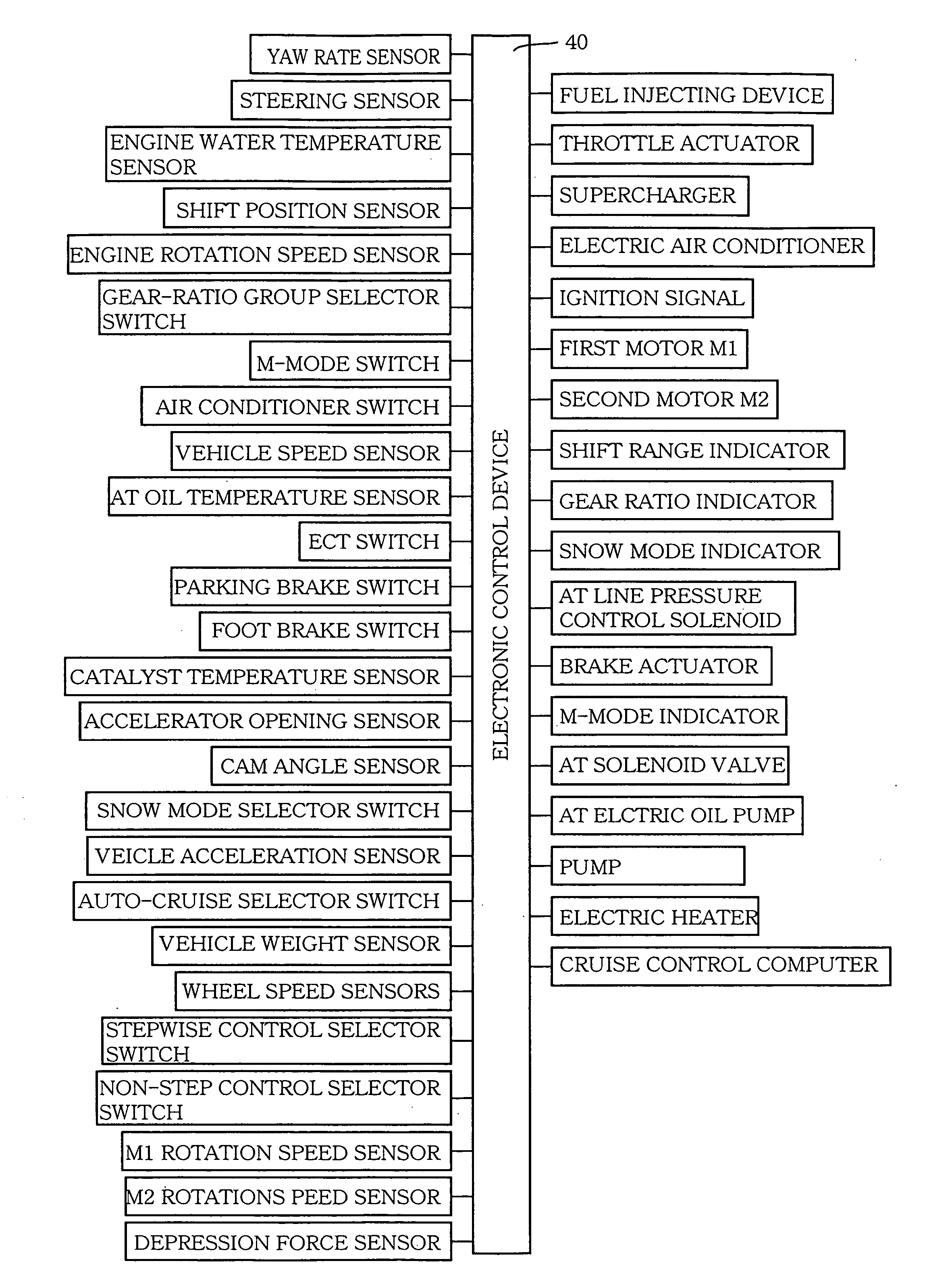
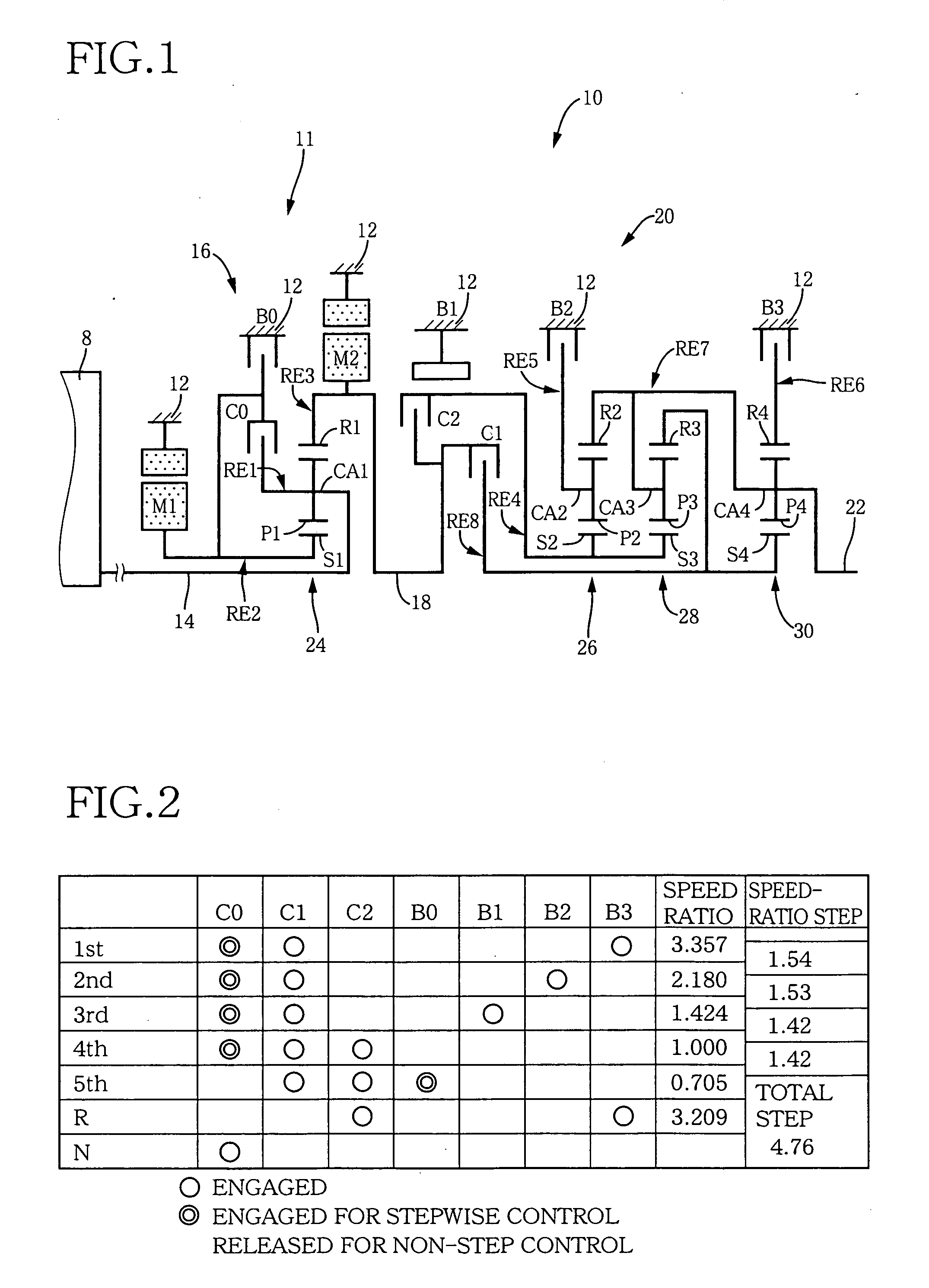
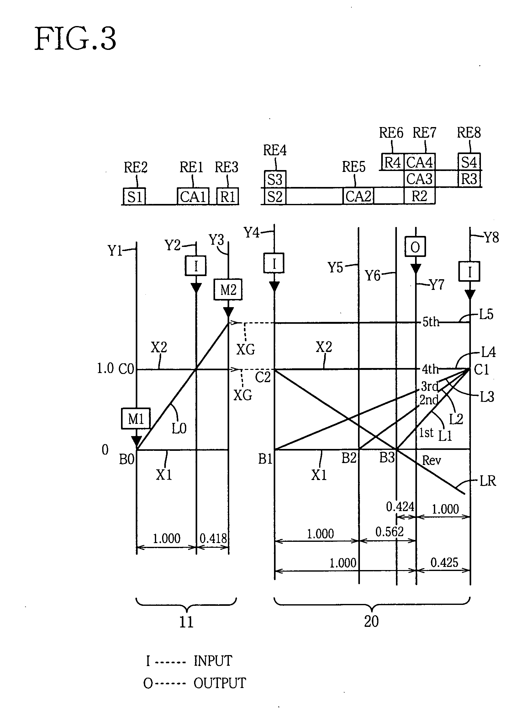
[0044]FIG. 1 is a schematic view for explaining a transmission system 10 constituting a portion of a driving device of a so-called “hybrid” automotive vehicle to which the present invention is applied. The hybrid vehicle additionally includes an electronic control device 40 shown in FIG. 4. In FIG. 1, the transmission system 10 includes an input shaft 14 as a rotary input member, a non-step (i.e., continuous) speed change portion 11 as a power transmission device, an automatic speed change portion 20 as a stepwise automatic transmission, and an output shaft 22 as a rotary output member all of which are provided, in series, on a common axis in a transmission case 12 (hereinafter referred to as the “case 12”) as a non-rotary (i.e., stationary) member that is fixed to a body of the vehicle. The non-step speed change portion 11 is connected to the input shaft 14 directly, but it may be connected indirectly via, e.g., a pulsation absorbing damper (i.e., a vibration damping device), not s...

second embodiment

[0105]FIG. 11 is a schematic view for explaining a transmission system 70 constituting a portion of another driving device to which the present invention is applied; FIG. 12 is an operation table representing a relationship between speed steps of the transmission system 70 and corresponding combinations of respective operating states of hydraulically operated frictional coupling devices; and FIG. 13 is a collinear chart for explaining speed change operations of the transmission system 70.

[0106] Like the transmission system 10 employed in the first embodiment, the transmission system 70 employed in the present, second embodiment includes the non-step (i.e., continuous) speed change portion 11 including the first electric motor M1, the power transfer 16, and the second electric motor M2. In addition, the transmission system 70 includes an automatic speed change portion 72 that is provided between the non-step speed change portion 11 and the output shaft 22, is connected, in series, t...

third embodiment

[0114]FIG. 14 shows a seesaw-type switch 44 (hereinafter, simply referred to as the switch 44) as a portion of a speed change state manual selector that is manually operable by a driver for selectively switching the power transfer 16 to the differential state or to the non-differential state, i.e., the transmission system 10, 70 to the non-step speed change state or the stepwise speed change state. The switch 44 may be provided, in each of the above-described first and second embodiments, in the hybrid vehicle such that the switch 44 is manually operable by the driver. This switch 44 enables the driver to run the vehicle in a desired or selected one of the different speed change control modes. The switch 44 includes a first portion that is labeled “STEP” and corresponds to the stepwise speed change control mode, and a second portion that is labeled “NON-STEP” and corresponds to the non-step speed change control mode. When the driver pushes the first or second portion of the switch 4...


PUM


Abstract

A control apparatus for a vehicle's driving device including (A) a non-step speed change portion including (a1) a differential device that distributes an output of an engine to a first electric motor and a transmission member, and (a2) a second electric motor provided in a power transmission path from the transmission member to drive wheels, and (B) an automatic speed change portion constituting a portion of the power transmission path, the control apparatus including a vehicle behavior stabilization controller for stabilizing a behavior of the vehicle when the behavior of the vehicle is unstable; a coupling device which is selectively switchable to (a) a released state thereof in which the coupling device places the non-step speed change portion in a non-step speed change state thereof in which the non-step speed change portion is operable as an electric CVT (continuously variable transmission), and (b) an engaged state thereof in which the coupling device places the non-step speed change portion in a stepwise speed change state thereof in which the non-step speed change portion is not operable as the electric CVT; and a vehicle-stabilization-related switching controller which switches, when the vehicle behavior stabilization controller performs a vehicle behavior stabilization control, the coupling device to the released state thereof.

Description

[0001] The present application is based on Japanese Patent Application No. 2004-203945 filed on Jul. 9, 2004, the contents of which are incorporated herein by reference. BACKGROUND OF THE INVENTION [0002] 1. Field of the Invention [0003] The present invention relates to a driving device of a vehicle that includes a differential device having a differential function and thereby operating as a speed change device, i.e., a transmission, and particularly to the art of assuring that the driving device can employ, e.g., an electric motor having a small capacity. [0004] 2. Related Art Statement [0005] There is known a driving device of a vehicle that includes a differential device that distributes an output of an engine to a first electric motor and an output shaft; and a second electric motor that is provided between the output shaft of the differential device, and drive wheels of the vehicle. An example of a driving device of a hybrid vehicle is disclosed by each of Japanese Patent Appli...

Claims


Application Information

Patent Timeline
IPC IPC(8): B60T13/74B60K6/365B60K6/445B60K6/547B60L15/20B60L50/16B60W10/06B60W10/08B60W10/10B60W10/18F16H59/50F16H59/54F16H61/00F16H61/02F16H61/68F16H61/684F16H61/686
CPCB60K6/445B60T8/1755B60T2201/14Y02T10/6239B60W10/101B60W30/02Y02T10/7258B60W10/02Y02T10/62Y02T10/72
Inventor TABATA, ATSUSHITAGA, YUTAKA
Owner TOYOTA JIDOSHA KK
Why Eureka
Try Eureka