Lighting unit for flat panel display device

a flat panel display device and light source technology, applied in lighting, heating apparatus, printing, etc., can solve the problems of increasing the chimney effect, increasing the heat dissipation, and heat also dissipating through the rear wall, and achieves effective heat dissipation, high luminous efficiency, and uniform brightness distribution.

Inactive Publication Date: 2006-01-12
WAMMES & PARTNER
View PDF3 Cites 0 Cited by
  • Summary
  • Abstract
  • Description
  • Claims
  • Application Information

AI Technical Summary

Benefits of technology

[0004] Thus one object of the invention is to create effective heat dissipation and uniform brightness distributi...

Problems solved by technology

Thus, heat also dissipates through the rear wall.
As the heat generated by the lamps increases, the heat...

Method used


Image

  • Lighting unit for flat panel display device
  • Lighting unit for flat panel display device
  • Lighting unit for flat panel display device

Examples


Embodiment Construction

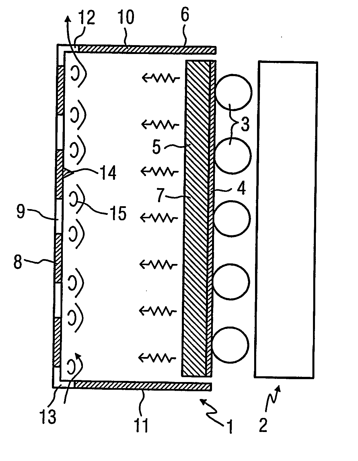
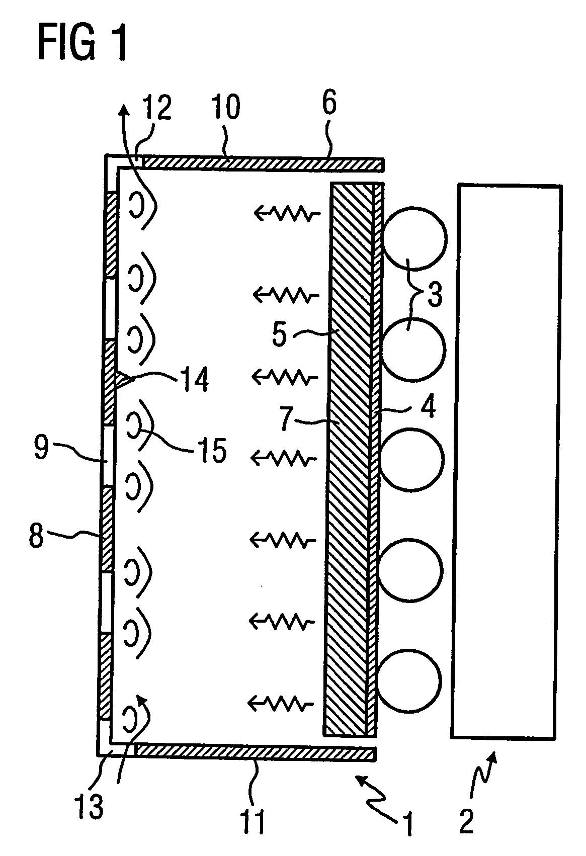
[0016]FIG. 1 is a schematic representation of a lighting unit 1 that provides backlighting for a flat panel display 2, in this case a liquid crystal display. The lighting unit 1 and the flat panel display 2 are operated substantially in a vertical working position, as depicted in FIG. 1. On its light-emitting side, the lighting unit 1 is provided with a plurality of lamps 3 distributed over the light-emitting area and parallel to each other. In this case, the lamps 3 are cold cathode fluorescent tubes. The backside of the lamps is in thermal contact with a heat-conducting wall 5 of a hollow box 6, with a reflective layer 4 placed therebetween. The backside of the hollow box is illustrated in FIG. 2. The heat-conducting wall 5 comprises a comparatively thick aluminum plate, which, on the side 7 facing the interior of the hollow box 6, is dyed or coated black. The other parts of the hollow box 6 are made of materials that conduct heat relatively poorly, in this case high-grade steel, ...


PUM


Abstract

A lighting unit (1) preferably providing backlighting for a flat display device (2) and operating substantially in a vertical working position. The lighting unit (1) includes lamps (3), which are in thermal contact with a heat-conducting wall (5) of a hollow box (6). The lamps (3) make thermal contact with the heat-conducting wall (5) on the side opposite the light-emitting side of the lighting unit (1). The hollow box (6) is provided with a rear wall (8) that runs essentially parallel to the heat-conducting wall (5) and has openings (9) which are distributed across the area thereof. A top sidewall (10) and a bottom sidewall (11) are provided with additional openings (12, 13) in zones that lie closer to the rear wall (8). Preferably, the sidewalls do not have openings in zones located closer to the heat-conducting wall (5) than the additional openings (12, 13).

Description

[0001] This is a Continuation of International Application PCT / DE2003 / 003256, with an international filing date of Sep. 30, 2003, which was published under PCT Article 21(2) in German, and the disclosure of which is incorporated into this application by reference.FIELD AND BACKGROUND OF THE INVENTION [0002] The invention relates to a lighting unit, which provides backlighting for a flat panel display device. [0003] Flat panel display devices that are not self-luminous, such as liquid crystal displays, require backlighting in the form of a lighting unit that is as flat as possible. The lighting unit typically has a plurality of lamps, which are distributed across a light-emitting area of the lighting unit. The lamps are usually fluorescent lamps, for example, cold cathode fluorescent lamps (CCFLs). The light of the lighting unit is uniformly distributed over the light-emitting area by means of light-guiding elements, diffusing screens or the like. Light exiting the rear of the lamps ...

Claims


Application Information

Patent Timeline
IPC IPC(8): H01J1/02H01J61/52H01J7/24H01K1/58F21V7/05F21V29/00G02F1/13357
CPCF21V7/05F21V29/004F21V29/83G02F1/133604G02F2001/133628F21V29/2212F21V29/763G02F1/133628G02F1/1335
Inventor WAMMES, KLAUS
Owner WAMMES & PARTNER
Why Eureka
Try Eureka