Drive control apparatus and method of alternating current motor

a technology of alternating current motor and control apparatus, which is applied in the direction of motor/generator/converter stopper, electronic commutator, dynamo-electric converter control, etc., can solve the problem of low torque response of a motor, motor output torque to have an overshoot state, and torque response to be degraded

Active Publication Date: 2006-01-12
TOYOTA JIDOSHA KK +1
View PDF5 Cites 32 Cited by
  • Summary
  • Abstract
  • Description
  • Claims
  • Application Information

AI Technical Summary

Benefits of technology

[0009] To achieve the aforementioned advantage, the drive control apparatus of the present invention, which controls an AC motor subjected to rotational drive by applying rectangular wave voltage thereto, comprises: actual torque detection means for detecting an actual torque value outputted from the AC motor; estimated torque calculation means for calculating an estimated torque value based on a motor model with the AC motor in a simulated state; and voltage phase calculation means for calculating a voltage phase based on the actual torque value, the estimated torque value and a predetermined command torque value, wherein the voltage phase calculation means adds an actual parameter based on the actual torque value calculated in the calculation process of the voltage phase to an estimated parameter based on the estimated torque value in a predetermined proportion, and calculates the voltage phase based on the obtained value.
[0010] A drive control apparatus according to another embodiment of the present invention, controlling an AC motor subjected to rotational drive by applying rectangular wave voltage thereto, comprises: estimated torque calculation means for calculating an estimated torque value base...

Problems solved by technology

However, use of the low pass filter causes a time lag in the obtained output torque value, thus degrading torque response.
The drive control apparatuses disclosed in Japanese Patent Laid-Open Publication Nos. 2001-28892 and 2000-50689, which only feed back the output torque, have a disadvantage that the torque response of a motor is low.
Therefore, there is a problem that a c...

Method used


Image

  • Drive control apparatus and method of alternating current motor
  • Drive control apparatus and method of alternating current motor
  • Drive control apparatus and method of alternating current motor

Examples


Embodiment Construction

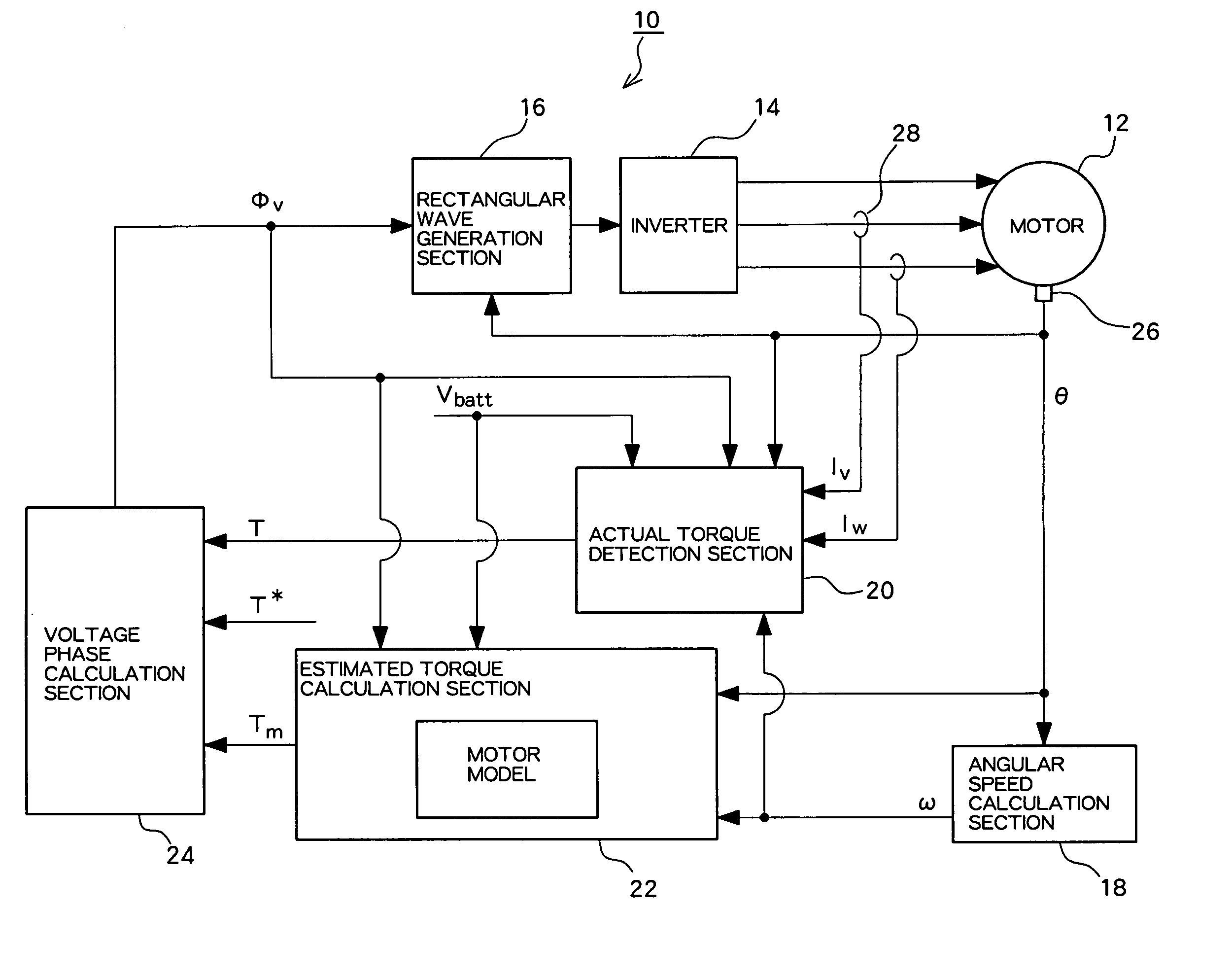
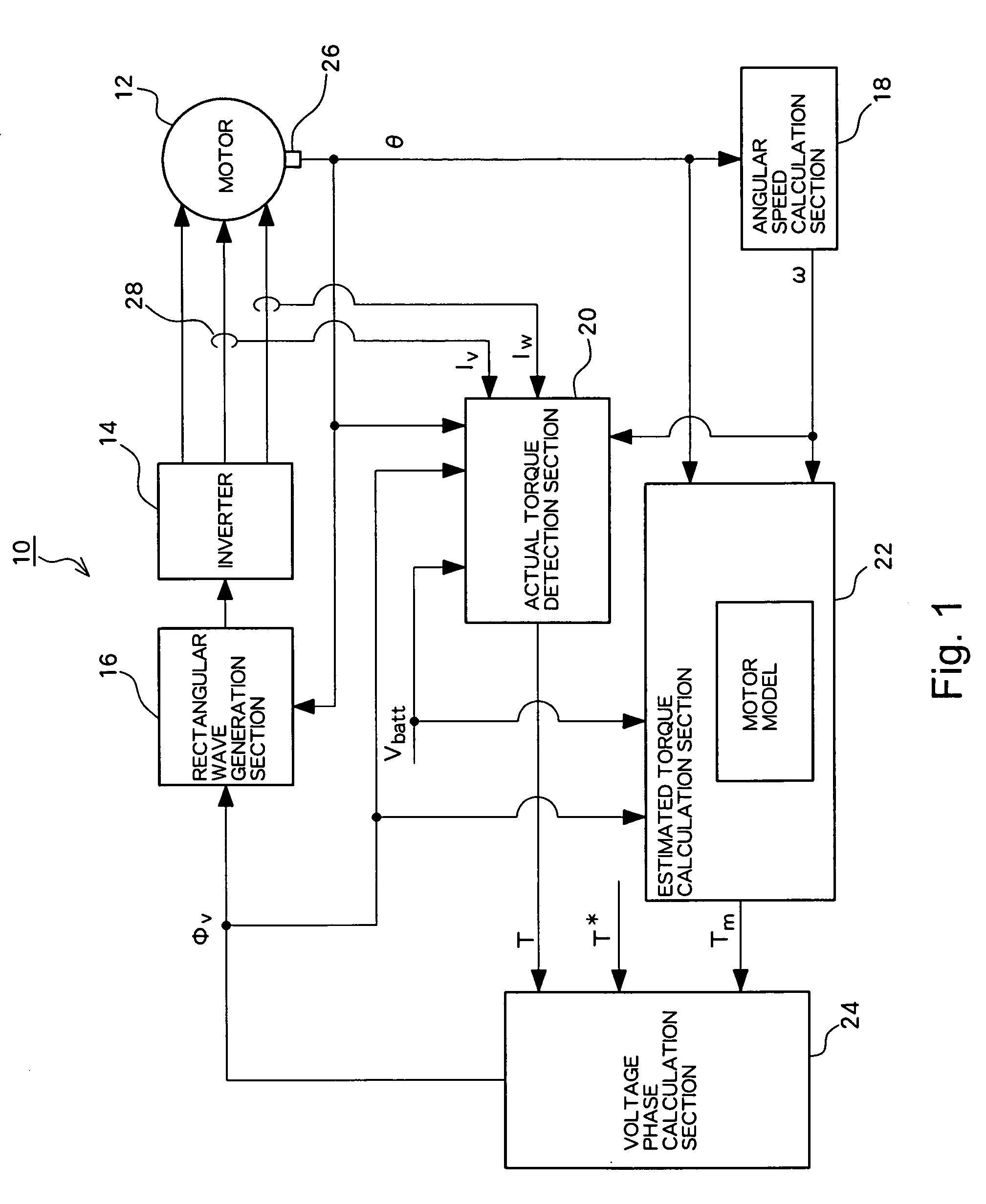
[0028] Hereinafter, with reference to the drawings, the description will be made of embodiments according to the present invention. FIG. 1 is a basic schematic block diagram of a drive control apparatus for an AC motor 12 according to one embodiment of the present invention. The input-output relationship of each section shown in FIG. 1 is a typical example and may be a relationship other than the one illustrated.

[0029] The drive control apparatus 10 controls the AC motor 12 driven by a rectangular wave voltage, and calculates a voltage phase φv corresponding to a predetermined command torque value T* and applies rectangular wave voltage to the AC motor 12.

[0030] An inverter 14 is connected to the AC motor 12. The inverter 14 receives power supply from a power source, not shown, and passes current through stator windings for respective U, V and W phases of the AC motor 12. On a power supply line from the inverter 14 to the AC motor 12, there is provided a current sensor 28 to detec...


PUM


Abstract

A drive control apparatus, which controls an AC motor subjected to rotational drive by applying a rectangular wave voltage thereto, comprising: an actual torque detection section for detecting an actual torque value T outputted from the AC motor; an estimated torque calculation section for calculating an estimated torque value Tm based on a motor model with the AC motor in a simulated state; and a voltage phase calculation section wherein the voltage phase calculation section calculates a first voltage phase φfb based on the actual torque value T and a command torque value T*, and a second voltage phase φff based on the estimated torque value Tm and the command torque value T* respectively, and outputs a value obtained by making the voltage phase subjected to weighting addition, as a voltage phase φv.

Description

BACKGROUND OF THE INVENTION [0001] 1. Field of the Invention [0002] The invention relates to a drive control apparatus and method for controlling an alternating current motor, hereinafter referred to as an “AC motor”, subjected to rotational drive by applying a rectangular wave voltage thereto. [0003] 2. Description of the Related Art [0004] For outputting a predetermined command torque from a motor, it is widely known to use a technique of controlling voltage applied to the motor. For example, Japanese Patent Laid-Open Publication Nos. 2001-28892 and 2000-50689 respectively disclose a drive control apparatus which calculates such a voltage phase so as to eliminate deviation of an output torque value from a command torque value by feeding back an output torque value of a motor. Japanese Patent Laid-Open Publication No. 2001-28892 obtains an output torque value based on respective phase currents detected by a detector, a command voltage value, and an angular speed. On the other hand,...

Claims


Application Information

Patent Timeline
IPC IPC(8): H02P7/00H02P27/04H02P6/06H02P6/08H02P6/16H02P6/17H02P21/00H02P21/13H02P21/14H02P21/18H02P21/24H02P21/28H02P23/12H02P23/14
CPCH02P21/0035H02P21/22
Inventor INAGUMA, YUKIONAKAI, HIDEOOHTANI, HIROKIOKAMURA, MASAKI
Owner TOYOTA JIDOSHA KK
Why Eureka
Try Eureka