Electrical touch sensor and human interface device using the same

a technology of touch sensor and human interface, applied in the field of touch sensor, can solve the problems of difficult to minimize the resultant product, complicated structure, and difficult to minimize the conventional electrical touch sensor

Active Publication Date: 2006-01-12
III HLDG 2
View PDF6 Cites 79 Cited by
  • Summary
  • Abstract
  • Description
  • Claims
  • Application Information

AI Technical Summary

Benefits of technology

[0027] Therefore, to solve the problem described hereinabove, an object of the present invention is to provide an electrical touch sensor capable of prec...

Problems solved by technology

The push button requires a mechanical contact for detecting whether an object pushes a button, and a spring device for turning the button back, to make it difficult to minimize the resultant product and make its structure complicated, while its manufacturing cost is inexpensive.
Therefore, it is difficult to minimize t...

Method used


Image

  • Electrical touch sensor and human interface device using the same
  • Electrical touch sensor and human interface device using the same
  • Electrical touch sensor and human interface device using the same

Examples


first embodiment

[0068]FIG. 4 is a circuit diagram illustrating the electrical touch sensor of FIG. 3.

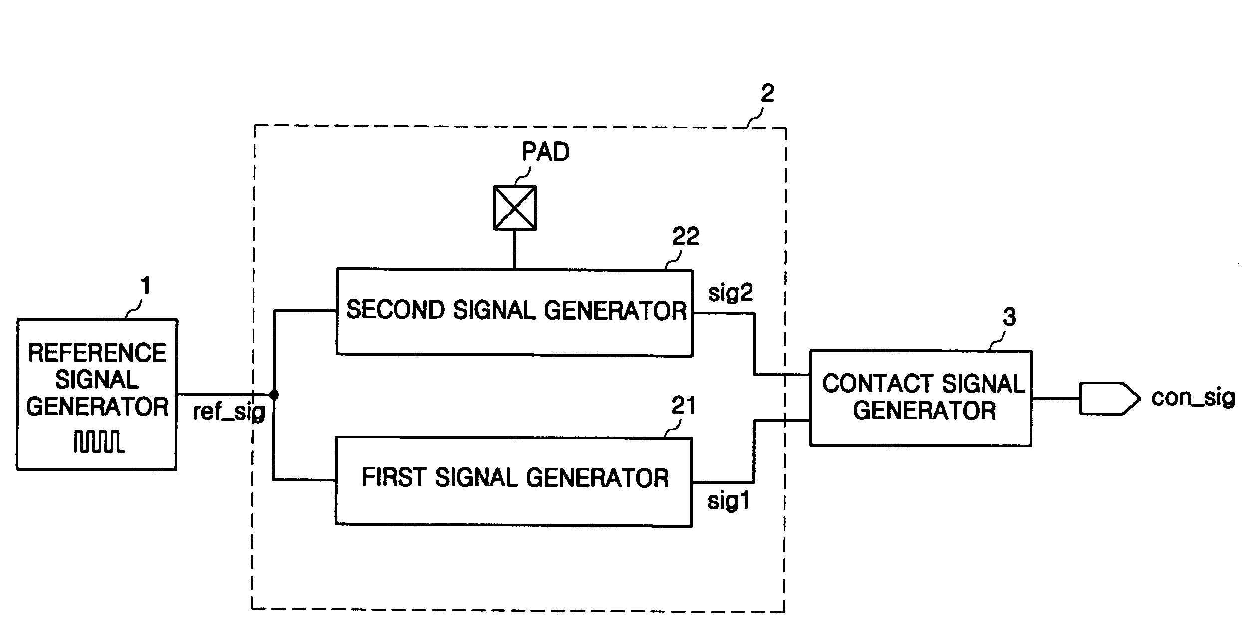
[0069] Referring to FIG. 4, the electrical touch sensor of the present invention includes a reference signal generator 1, a touch detection part 210 having first and second signal generators 211 and 212, and a contact signal generator 31.

[0070] The first signal generator 211 includes a first resistor R11 disposed between a reference signal generator 1 and a contact signal generator 31, and a first capacitor C11 disposed between the first resistor R11 and the contact signal generator 31 and connected to a ground voltage VGND. The second signal generator 212 includes a second resistor R12 disposed between the reference signal generator 1 and the contact signal generator 31, and a touch pad PAD disposed between the second resistor R12 and the contact signal generator 31 and connected through an individual signal line. The contact signal generator 31 includes a D-flip / flop D_F / F, and a low-band pass fi...

second embodiment

[0083]FIG. 6 is a circuit diagram illustrating the electrical touch sensor of FIG. 3.

[0084] Referring to FIG. 6, the electrical touch sensor of the present invention includes a reference signal generator 1, a touch detection part 220 having first and second signal generators 221 and 222, and a contact signal generator 32.

[0085] Referring to FIG. 6, a first signal generator 221 includes a first resistor R21 and a first input buffer B21 connected in series to a reference signal generator 1; a second signal generator 222 includes a second resistor R11 and a second input buffer B22 connected in series to the reference signal generator 1, and a touch pad PAD disposed between the second resistor R22 and the second input buffer B22 and connected through an individual signal line; and a contact signal generator 32 includes an exclusive OR device XOR1 for exclusively logically summing output signals sig1 and sig2 of the first and second input buffers B21 and B22, and a low-band pass filter ...


PUM


Abstract

An electrical touch sensor is provided. The electrical touch sensor includes: a touch detection part having at least one touch pad and generating a first signal having a same delay time regardless of whether the object is in contact with the touch pad and a second signal having a varied delay time according to whether the object is in contact with the touch pad; and a contact signal generator generating a contact signal in response to the delay time-difference between the first and second signals. Therefore, it is possible to increase operation reliability by precisely determining whether the object is in contact with the pad, when the object has charge accumulation characteristics more than a certain level, although its conductive is insufficient. In addition, the electrical touch sensor can determine whether the object is in contact with the pad using only one pad to reduce a layout area of a product.

Description

[0001] This U.S. nonprovisional patent application claims priority under 35 U.S.C. § 119 of Korean Patent Application 2004-40537 filed on Jun. 03, 2004, and Korean Patent Application 2005-23382 filed on Apr. 21, 2005, the entire contents of which are hereby incorporated by reference. BACKGROUND OF THE INVENTION [0002] 1. Field of the Invention [0003] The present invention relates to a touch sensor and, more particularly, to an electrical touch sensor for electrically detecting whether an object is touched and informing the result and a human interface device using the same. [0004] 2. Description of Related Art [0005] Generally, a touch sensor is classified into a push button operated in a mechanical manner, and an electrical touch sensor operated in a non-mechanical manner. [0006] The push button requires a mechanical contact for detecting whether an object pushes a button, and a spring device for turning the button back, to make it difficult to minimize the resultant product and ma...

Claims


Application Information

Patent Timeline
IPC IPC(8): G09G5/00
CPCG06F3/03543G06F2203/0339G06F3/0383G06F3/03547
Inventor JUNG, DEOK-YOUNGHONG, JAE-SURKSHIN, YOUNG-HO
Owner III HLDG 2
Why Eureka
Try Eureka