Ink jet recording apparatus and ink jet recording method

a recording apparatus and ink jet technology, applied in typewriters, printing, other printing apparatus, etc., can solve the problems of increasing the size of the jet head, increasing the size of the entire recording apparatus, and unable to achieve high speed driving of the ink jet head

Active Publication Date: 2006-01-12
KONICA MINOLTA INC
View PDF8 Cites 75 Cited by
  • Summary
  • Abstract
  • Description
  • Claims
  • Application Information

AI Technical Summary

Benefits of technology

[0115] Then, the same effects as those obtaina

Problems solved by technology

In the cases where the discharge lamps are attached to the ink jet head, the ink jet head increases in size, such that high speed driving of the ink jet head becomes impossible.
This, together with the increased size of the ink jet head, results in an increase in the size of the entire recording apparatus.
Also, the structure in which the discharge lamps and the ink jet head are connected via the optical fibers is indeed difficult to realize, because the optical fibers

Method used


Image

  • Ink jet recording apparatus and ink jet recording method
  • Ink jet recording apparatus and ink jet recording method
  • Ink jet recording apparatus and ink jet recording method

Examples


first embodiment

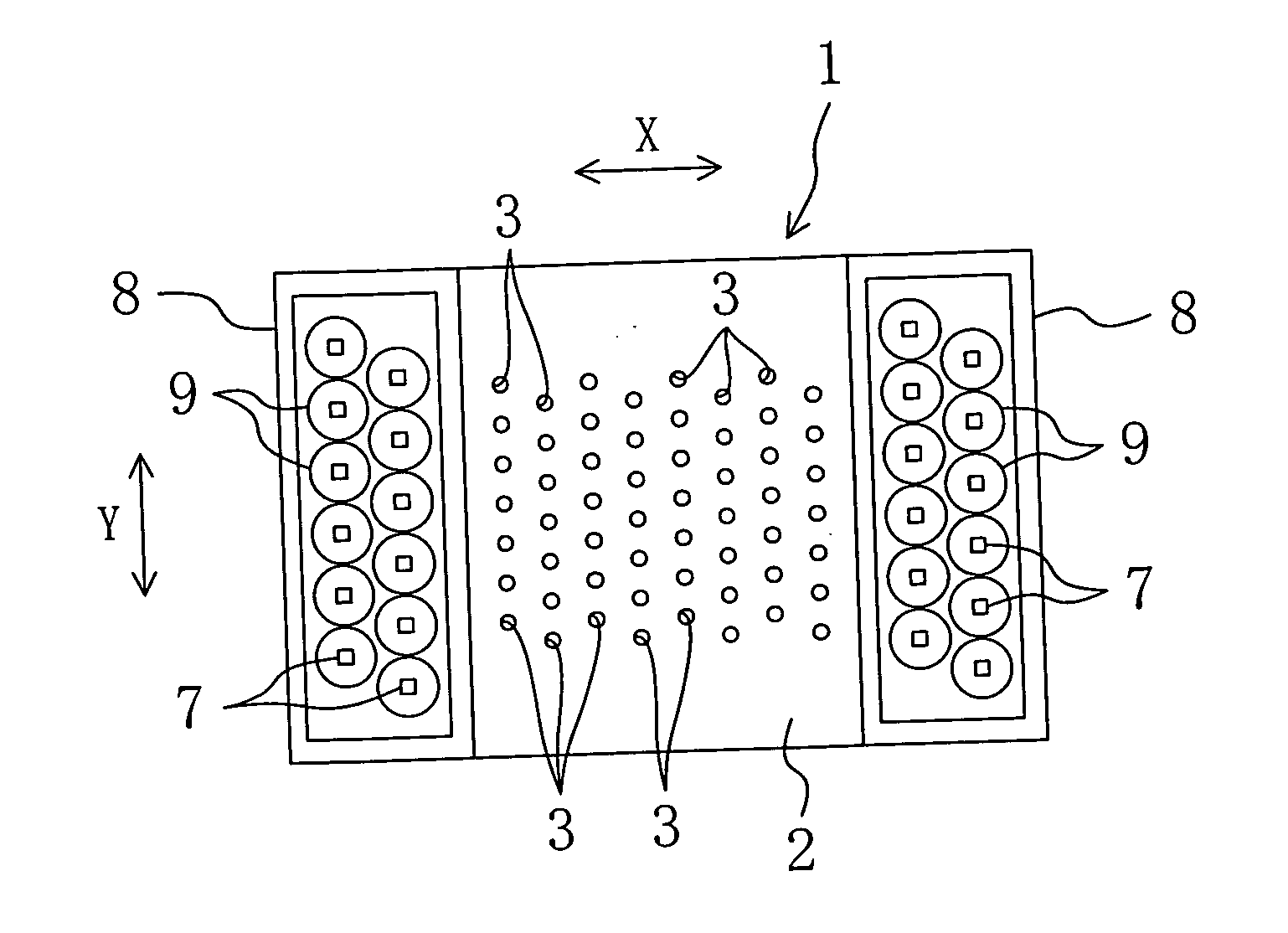
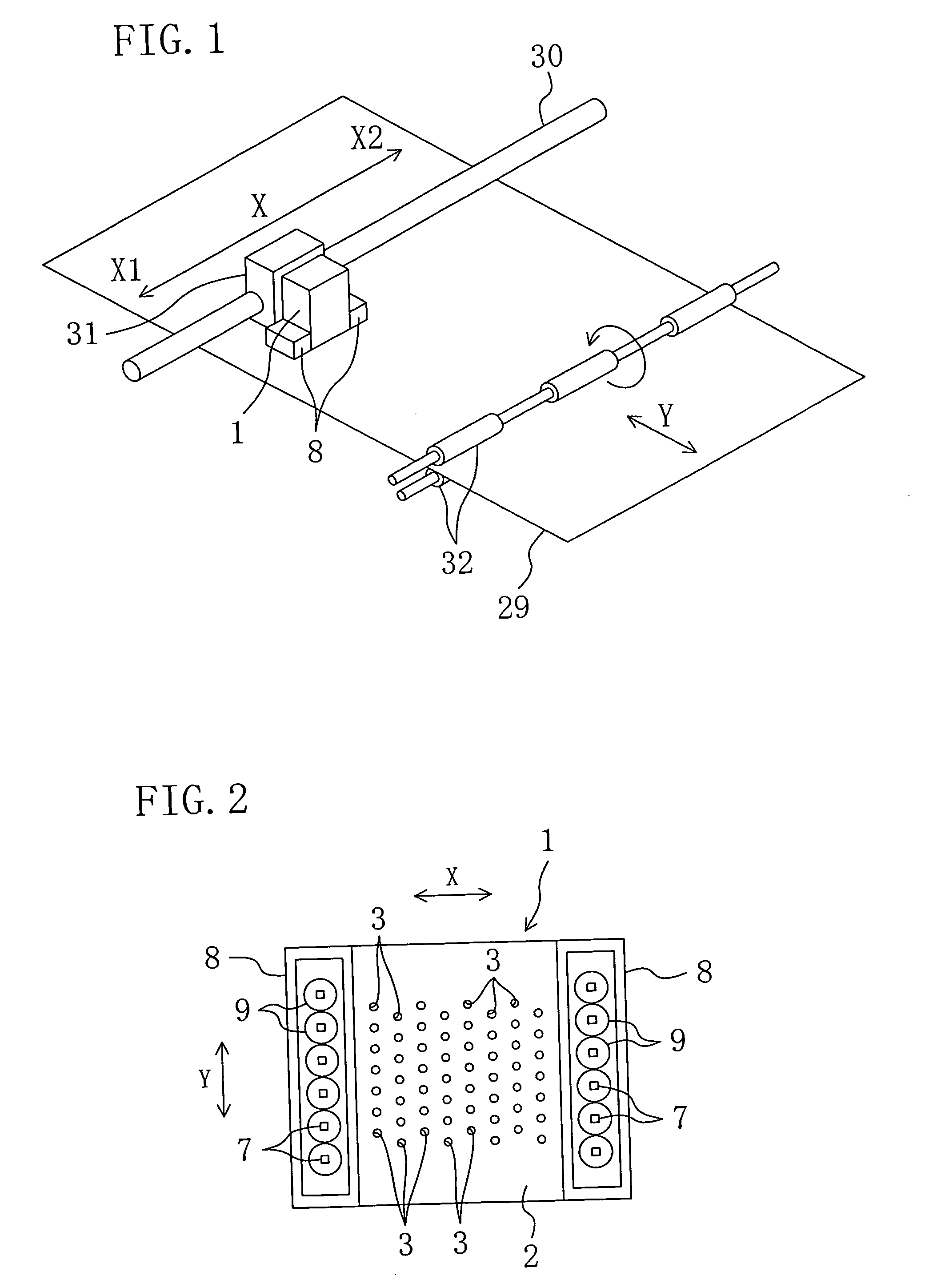
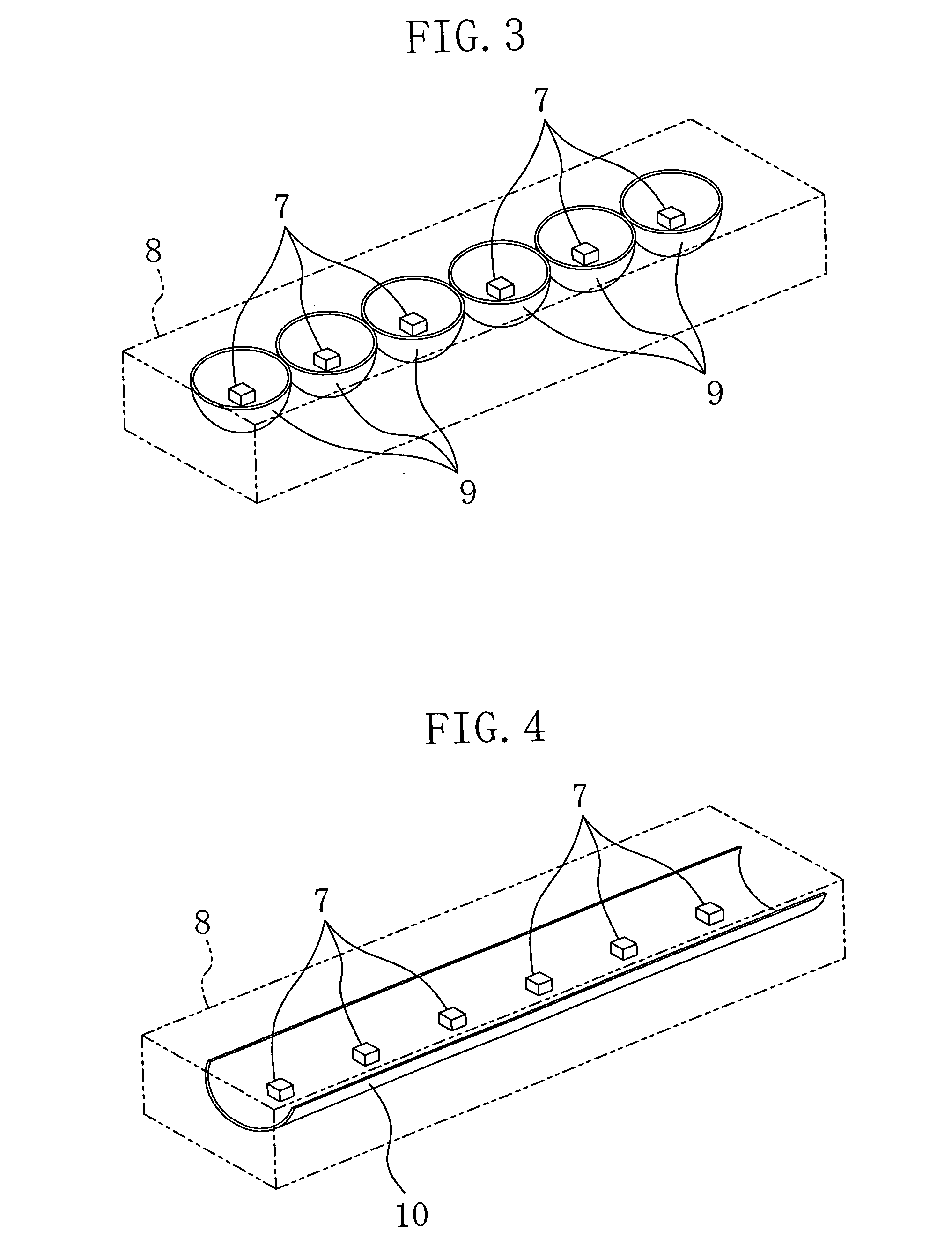
[0134]FIG. 1 schematically illustrates an ink jet recording apparatus according to a first embodiment of the present invention. The ink jet recording apparatus includes an ink jet head 1 which, as will be described later, ejects UV curable inks (photocurable inks) onto the recording surface (i.e., the upper surface) of a recording paper 29 serving as a recording medium. The ink jet head 1 is fixedly supported by a carriage 31, which is provided with a not-shown carriage motor. Being guided by a carriage shaft 30 that extends in the main scanning direction (i.e., the X direction shown in FIG. 1) parallel to the recording surface of the recording paper 29, the ink jet head 1 and the carriage 31 are reciprocated by the carriage motor in the main scanning direction between a position X1 that corresponds to one end of the width of the recording paper 29 and a position X2 that corresponds to the other end thereof. The carriage 31, the carriage shaft 30, and the carriage motor form a head ...

second embodiment

[0161]FIGS. 13 and 14 illustrate a second embodiment of the present invention, in which ink jet heads 1 are so-called line heads.

[0162] More specifically, in the second embodiment, a recording paper 29, fed from a feeding roller 41 which rotates clockwise as shown in FIG. 13, passes through a recording section, in which four ink jet heads 1 are disposed, and then is rolled up on a take-up roller 42 which rotates clockwise as shown in FIG. 13. The feeding roller 41, the take-up roller 42, and a plurality of guide rollers 43 formed in the recording section move the recording paper 29 substantially horizontally in the recording section in a predetermined direction (which is a direction going toward the take-up roller 42, i.e., the direction A shown in FIGS. 13 and 14) parallel to the recording surface (i.e., the upper surface) of the recording paper 29. In this manner, the feeding roller 41, the take-up roller 42 and the guide rollers 43 form a recording-medium moving mechanism for mo...


PUM


Abstract

An ink jet recording apparatus in which a UV curable ink is ejected from nozzle holes of an ink jet head. The ejected ink is attached onto a recording surface of a recording medium (recording paper), and is cured by irradiation with ultraviolet light. The ink jet head, or a moving member which moves together with the ink jet head, is provided with a plurality of ultraviolet light emitting diodes that emit the ultraviolet light to the ink attached onto the recording surface of the recording medium to cure the ink.

Description

TECHNICAL FIELD [0001] The present invention relates to ink jet recording apparatuses and ink jet recording methods in which a photocurable ink (a UV curable ink, in particular) is ejected from nozzle holes of an ink jet head. BACKGROUND ART [0002] A technique has been conventionally known, in which a UV-curable ink is ejected from nozzle holes of an ink jet head onto the recording surface of a recording medium, and the ink attached to the recording surface is cured by ultraviolet irradiation so as to prevent the ink from spreading and bleeding on the recording surface (see Japanese Laid-Open Publication Nos. 2002-137375, 2003-11334, 2003-11343, and 2003-127338, for example). [0003] As light sources of the ultraviolet light, discharge lamps such as mercury lamps and metal halide lamps are typically used. Such discharge lamps are attached to the ink jet head, so that ultraviolet light emitted by the discharge lamps is directly applied to the recording surface of a recording medium, a...

Claims


Application Information

Patent Timeline
IPC IPC(8): B41J2/01B41J3/54B41J11/00
CPCB41J11/002B41J3/543B41J11/00214B41J11/00218
Inventor OSHIMA, KENJITAKAO, SHIGEYUKI
Owner KONICA MINOLTA INC
Why Eureka
Try Eureka