
Projector

a projector and projector technology, applied in the field of projectors, can solve the problems the projector becomes taller, and the distortion occurs, and achieve the effect of increasing the adjusting step and the cost of the projector

Inactive Publication Date: 2006-01-12
SEIKO EPSON CORP
View PDF12 Cites 4 Cited by
  • Summary
  • Abstract
  • Description
  • Claims
  • Application Information

AI Technical Summary

Benefits of technology

The solution achieves high luminance and uniform brightness across the screen with reduced assembly costs and complexity, while maintaining a thin and shallow projector form factor, minimizing distortion and light loss.

Problems solved by technology

According to the former method using the plane mirror, although the rear projector has a relatively thin structure, distortion occurs and the projector becomes taller.
Also, not only the relatively large plane mirror makes the projector heavier but also the plane mirror incorporated in an actual projector, requires a special mechanism to adjust displacements of the projection optical system and the plane mirror, thereby increasing an adjusting step and resultantly a cost of the projector.
Also, according to the latter method, using the projection optical system formed by a plurality of concave and convex mirrors, although the projection display apparatus can project a relatively highly accurate image while maintaining a thin structure, and adjusting work in the case of incorporating a plane mirror can be eliminated, the projection optical system itself is hard to assemble and adjust, thereby resulting in an increased cost of the projection display apparatus.

Method used


Image

  • Projector
  • Projector
  • Projector

Examples


Embodiment Construction

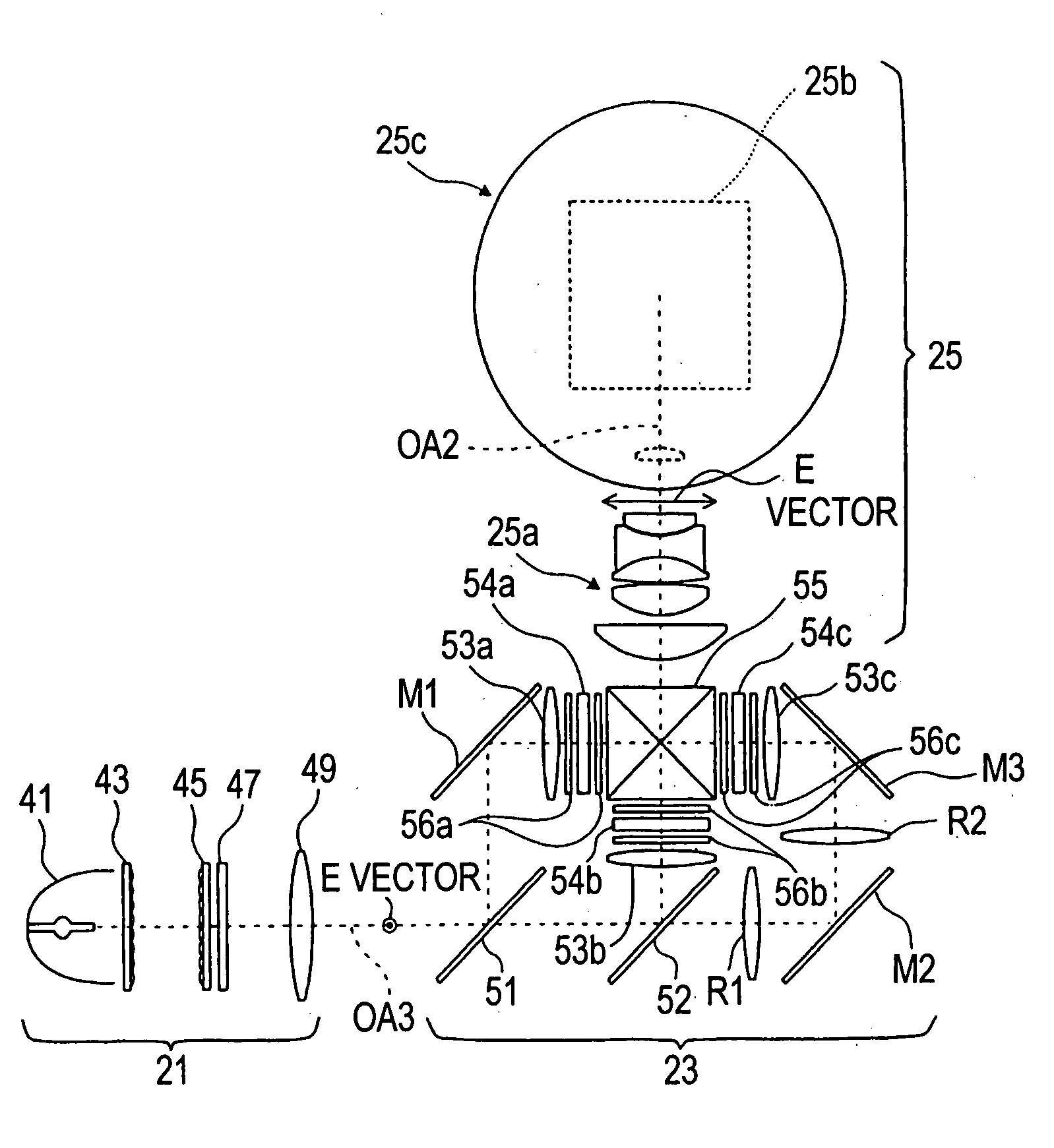
[0029] The structure of a projector according to an exemplary embodiment of the present invention will be described with reference to the accompanying drawings.

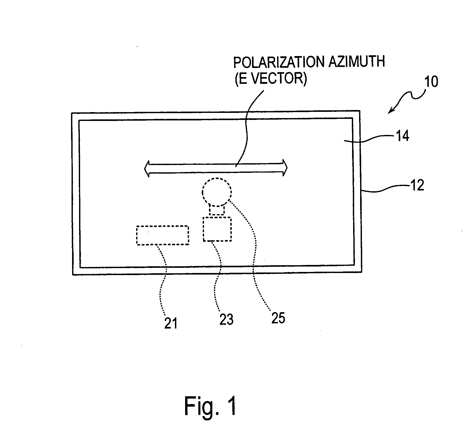
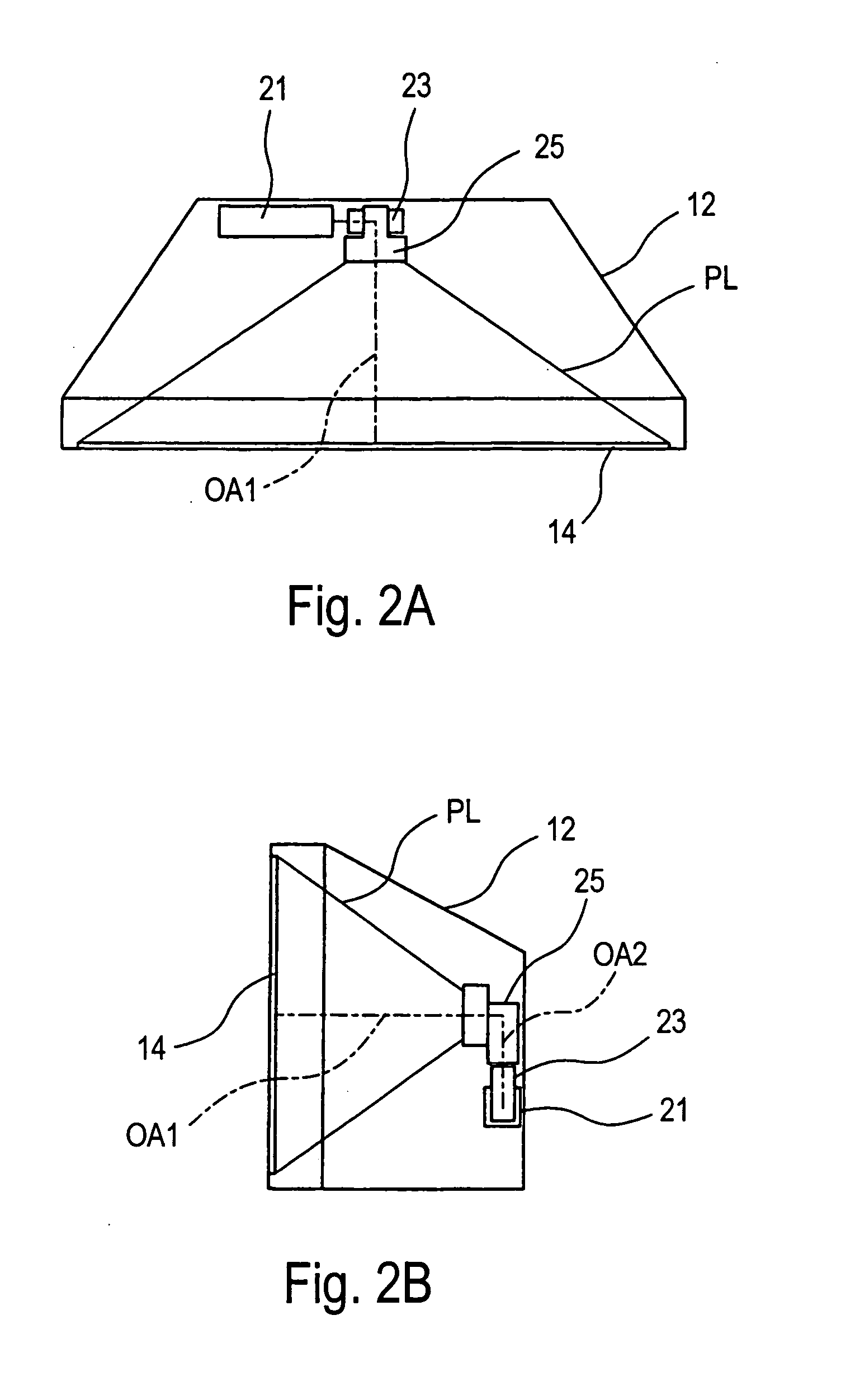
[0030]FIG. 1 illustrates the projector according to an exemplary embodiment, that is, an elevation view of the projector, and FIGS. 2(a) and 2(b) are respectively a perspective plan view and a perspective side view of the projector.

[0031] A projector 10 has a structure in which a main body formed by an optical system portion, an electrical circuit, and so forth is accommodated and held in a casing 12 serving as a housing.

[0032] The casing 12 has a screen 14 fixed across the entire front surface thereof in an embedded state. The screen 14 is a rear projection screen illuminated with projection light emitted from the inside of the casing 12 and has a rectangular shape which has a long width relative to the length. That is, which extends longer in the horizontal direction than in the vertical direction.

[0033]FIG. 3 is an ill...


PUM

PropertyMeasurementUnit
aspect ratioaaaaaaaaaa

Abstract

To provide a thin projector, such as a rear projector, formed by a less expensive projection optical system which is easy to assemble and install, and performing a highly accurate projection, projection light PL projected with a projection optical system onto a screen is linearly polarized light having a polarization azimuth along the longitudinal direction of the screen. With this arrangement, the right and left ends of the rear surface of the screen maintain a low reflectance, thereby reducing a loss in quantity of illumination light when passing through the screen, in other words, achieving high luminance of an image projected onto the screen while maintaining its uniformity of brightness.

Description

[0001] This is a Continuation of application Ser. No. 10 / 805,241 filed Mar. 22, 2004. The entire disclosure of the prior application is hereby incorporated by reference herein in its entirety.BACKGROUND OF THE INVENTION [0002] The present invention relates to a projector projecting an image by using spatial light modulation devices, such as liquid crystal panels. [0003] Among related art rear projection projectors, a shallow rear projector is prevailing, in which image light emitted from a projection optical system disposed behind and at the lower part of a screen is eventually reflected toward the forward direction, while being reflected at at least one plane mirror to secure a light path, so as to be projected onto the screen See Japanese Unexamined Patent Application Publication No. 5-66482. [0004] A projection display apparatus in which a diagonal projection having a large magnification is possible by forming its projection optical system with a plurality of concave and convex m...

Claims


Application Information

Patent Timeline
Patent Type & Authority Applications(United States)
IPC IPC(8): G03B21/14G02F1/13G02F1/1335G03B21/00G03B21/10G03B21/28G03B21/62H04N9/31
CPCH04N9/3105H04N9/3197H04N9/3167A46B13/02A46B2200/1066A61C17/34A61C17/349A61C17/40A61C2204/002
Inventor KARASAWA, JOJI
Owner SEIKO EPSON CORP
Learn More