Method and apparatus for maintaining focus and magnification of a projected image

a technology of projected image and focus, applied in the field of optical projection system, can solve the problems of image distance and magnification change, optical system imaging properties change,

Inactive Publication Date: 2006-01-12
COHERENT INC
View PDF8 Cites 10 Cited by
  • Summary
  • Abstract
  • Description
  • Claims
  • Application Information

AI Technical Summary

Problems solved by technology

One problem that arises during the projection operation is that a portion of the UV radiation being projected can be absorbed by optical elements of the optical projection system increasing the temperature of the elements and thereby ch

Method used


Image

  • Method and apparatus for maintaining focus and magnification of a projected image
  • Method and apparatus for maintaining focus and magnification of a projected image
  • Method and apparatus for maintaining focus and magnification of a projected image

Examples


Embodiment Construction

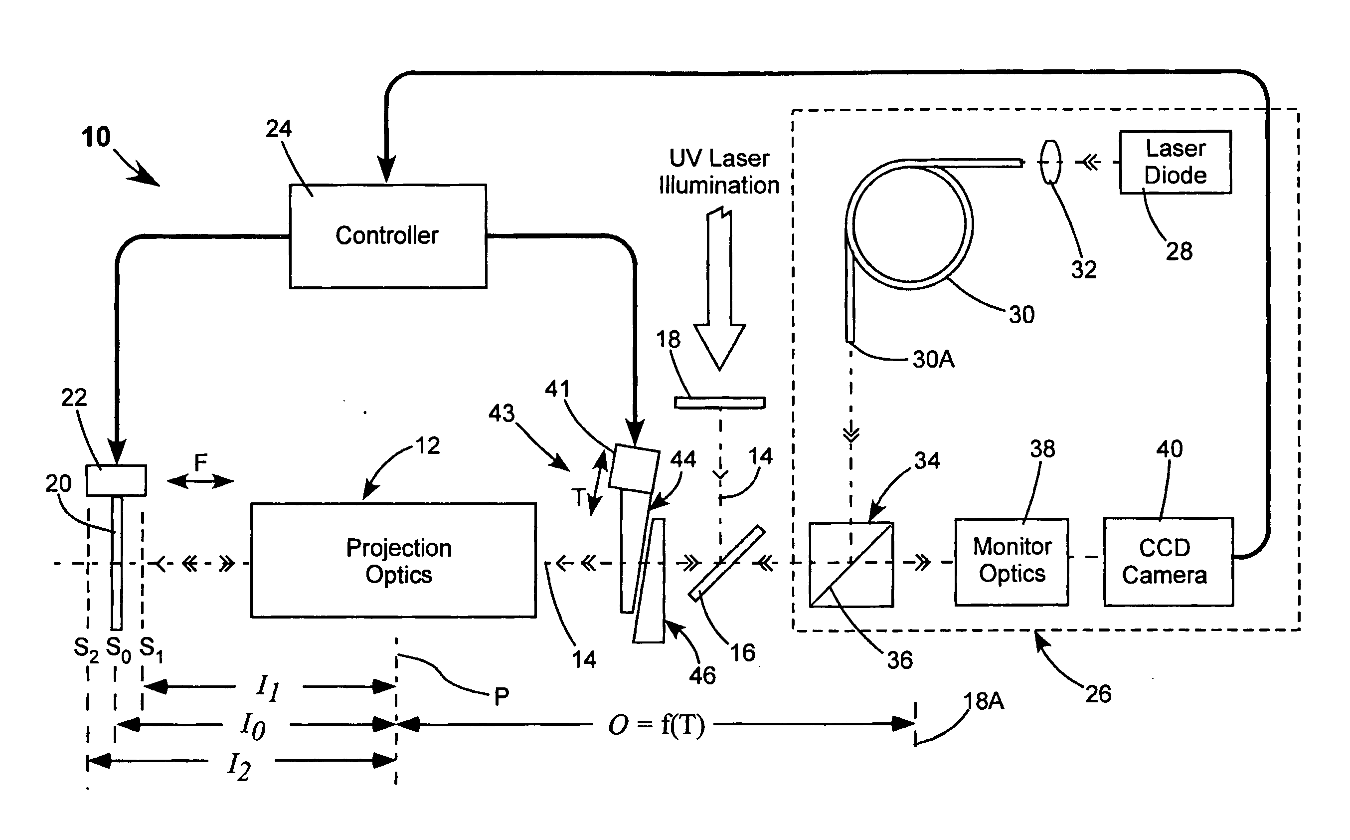
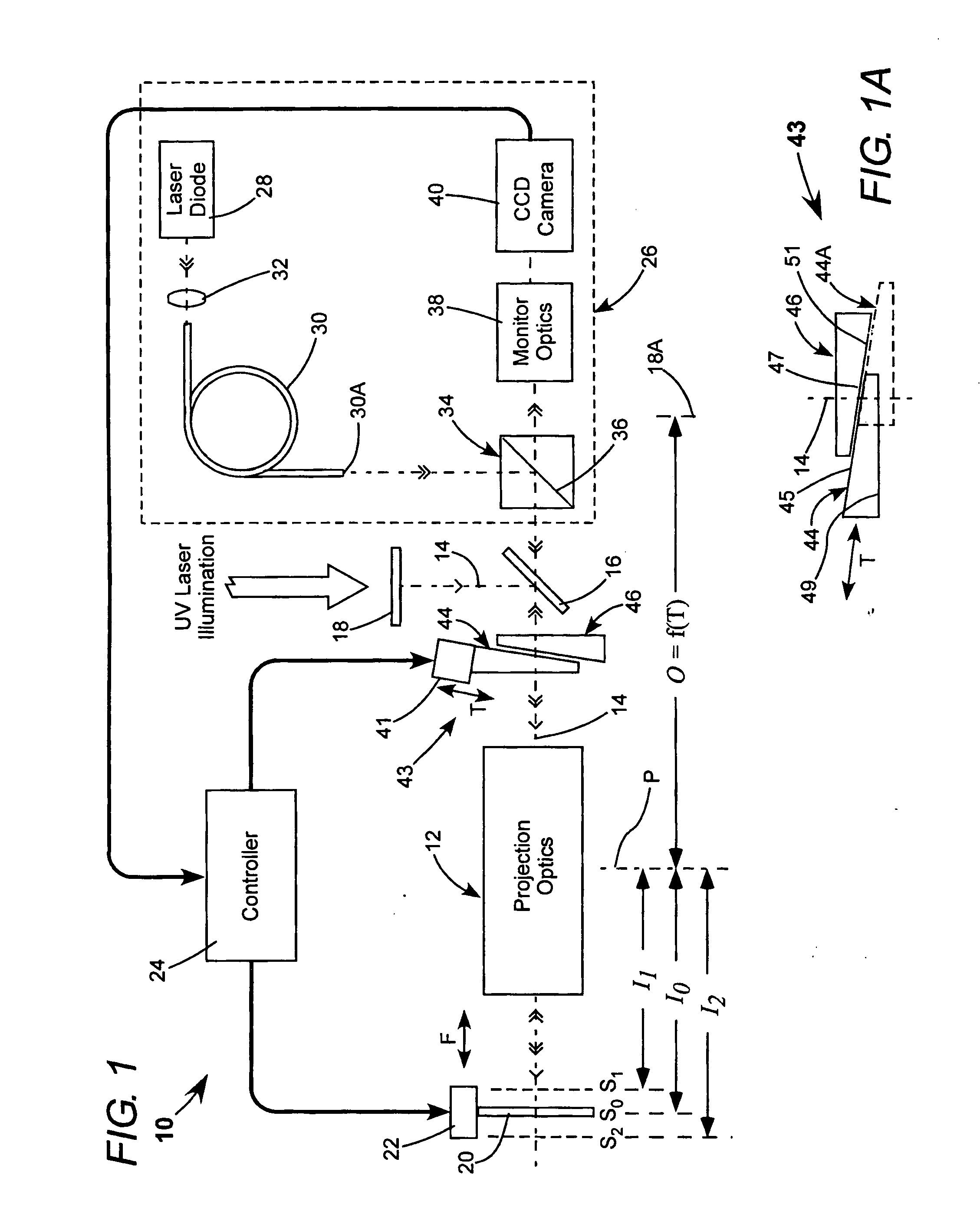
[0013] The FIG. 1 and FIG. 1A schematically illustrate a preferred embodiment 10 of apparatus in accordance with the present invention. Apparatus 10 includes projection optics 12 having a longitudinal optical axis (z-axis) 14 folded by a dichroic mirror 16. A mask 18, an image of which is to be projected, is located on the optical axis and illuminated by UV light from a laser and illumination optics (not shown). The general direction of propagation of UV light from the illuminated mask is indicated by single arrowheads. Projection optics 12 forms an image of the mask on a substrate (workpiece) 20 located at a position S0 at a focal distance I0 from a principal plane P of the projection optics. Substrate 20 is held on a platform 22, which is movable in forward and reverse directions along optical axis 14, responsive to commands from a system controller 24 as indicated by arrows F. Those skilled in the art will recognize that while the term “focus position” is used herein to describe ...


PUM


Abstract

A method for operating an optical projection system including projection optics is disclosed. The projection optics project an image of the object on the substrate at an image distance from the projection optics. The image has a size dependent on the size of the object and the ratio of the image distance to the optical distance of the object from the projection optics. The image distance can change with changes in the condition of the projection optics such as changes in the temperature of elements of the projection optics. The image distance is monitored. If the image distance changes, the substrate is moved to the new image distance and the optical distance of the object is correspondingly changed such that the ratio of the image distance to the object distance stays the same.

Description

PRIORITY [0001] This application claims the benefit of U.S. Provisional Application No. 60 / 586,191 filed Jul. 8, 2004, the disclosure of which is incorporated herein by reference.TECHNICAL FIELD OF THE INVENTION [0002] The present invention relates generally to using an optical projection system for projecting an image of a mask or reticle on a workpiece in laser material processing applications. The invention relates in particular to a method and apparatus for maintaining the projected image in focus while maintaining a predetermined dimension of the image independent of temperature-induced changes of the properties of the optical projection system. DISCUSSION OF BACKGROUND ART [0003] Ultraviolet (UV) laser radiation is often used in laser material processing applications. In several such operations material must be processed in a particular pattern. This is usually accomplished by making a (negative) mask or reticle representing a desired pattern and projecting an image of the mas...

Claims


Application Information

Patent Timeline
IPC IPC(8): G02B27/14
CPCG02B7/008G02B26/06G03F9/7034G03F9/7026G03F7/70308
Inventor FERBER, JOERGBURGHARDT, BERTHOLDSIMON, FRANK
Owner COHERENT INC
Why Eureka
Try Eureka