Optical antenna

a technology of optical antennas and antennas, applied in the field of optical antennas, can solve the problems of increasing cost and weight, time lag,

Inactive Publication Date: 2006-01-12
MITSUBISHI ELECTRIC CORP
View PDF1 Cites 22 Cited by
  • Summary
  • Abstract
  • Description
  • Claims
  • Application Information

AI Technical Summary

Benefits of technology

[0007] This offers an advantage of being able to set a plurality of optical transmitting and receiving directions without installing complicated mechanical elements.

Problems solved by technology

However, to control the transmitting and receiving direction of the laser beam, it is necessary to install the position adjuster and gimbal mechanism, which consist of complicated mechanical elements.
Thus, it has a problem of increasing the cost and weight.
In addition, it must move and adjust the optical fiber and casing three-dimensionally every time the object to be measured alters its position, which presents a problem of a time lag depending on the positioning time of the position adjuster and gimbal mechanism.

Method used


Image

  • Optical antenna
  • Optical antenna
  • Optical antenna

Examples


embodiment 1

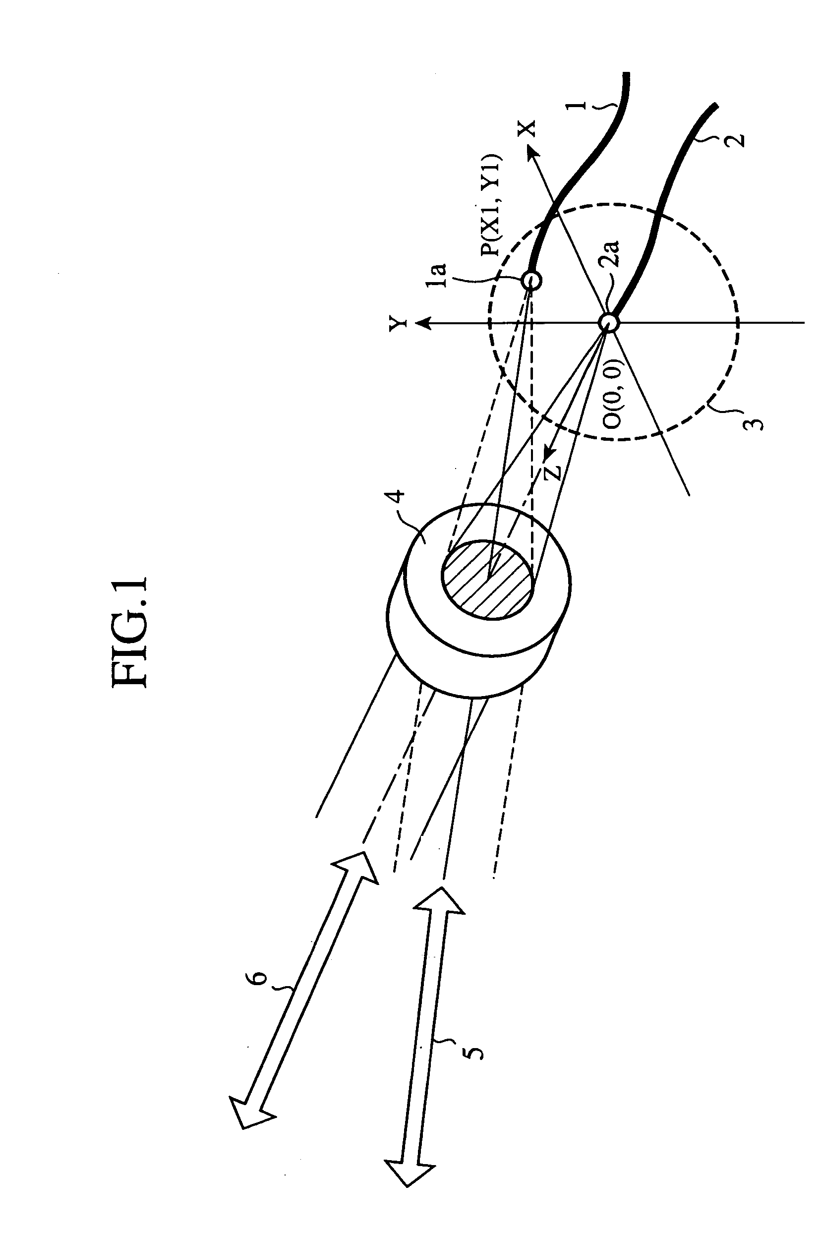
[0019]FIG. 1 is a diagram showing a configuration of an embodiment 1 of the optical antenna in accordance with the present invention. In FIG. 1, optical fibers 1 and 2 of an optical transmitting and receiving section (optical transmitting and receiving means) radiate laser beams (optical signals) to be transmitted from the optical transmitting and receiving section to an optical transmitting and receiving system 4, and receive laser beams focused by the optical transmitting and receiving system 4 and supply them to the optical transmitting and receiving section.

[0020] An optical element mount 3 places fiber ends 1a and 2a of the optical fibers 1 and 2 at different positions on an image plane of the optical transmitting and receiving system 4. The optical element mount 3 constitutes an arrangement means. The optical transmitting and receiving system 4 consists of a transmission lens made from an imaging optical system such as a photographic objective, and transmits, when the fiber e...

embodiment 2

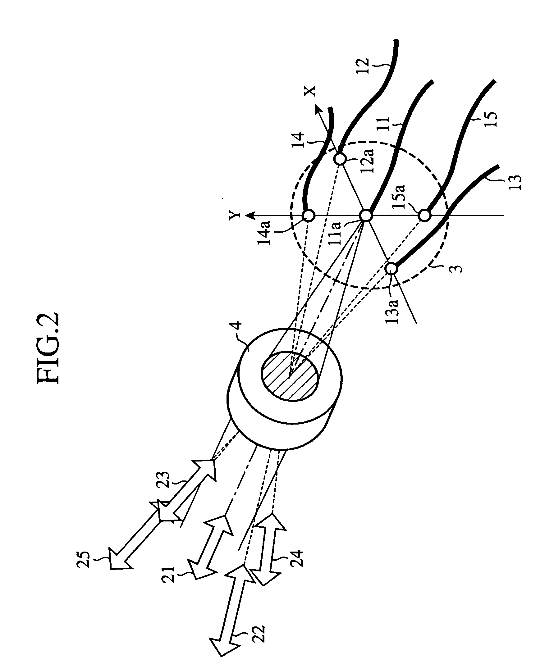
[0035]FIG. 2 is a diagram showing a configuration of an embodiment 2 of the optical antenna in accordance with the present invention. In FIG. 2, since the same reference numerals designate the same or like portions to those of FIG. 1, their description will be omitted here.

[0036] Optical fibers 11-15 of an optical transmitting and receiving section radiate laser beams to be transmitted from the optical transmitting and receiving section to the optical transmitting and receiving system 4. At the same time, the optical fibers 11-15 receive the laser beams focused by the optical transmitting and receiving system 4, and supply them to the optical transmitting and receiving section.

[0037] Optical transmitting and receiving directions 21-25 are directions of the laser beams set by the optical antenna.

[0038] The foregoing embodiment 1 is described by way of example in which the laser beams have fixed two directions as the optical transmitting and receiving directions. However, when the ...

embodiment 3

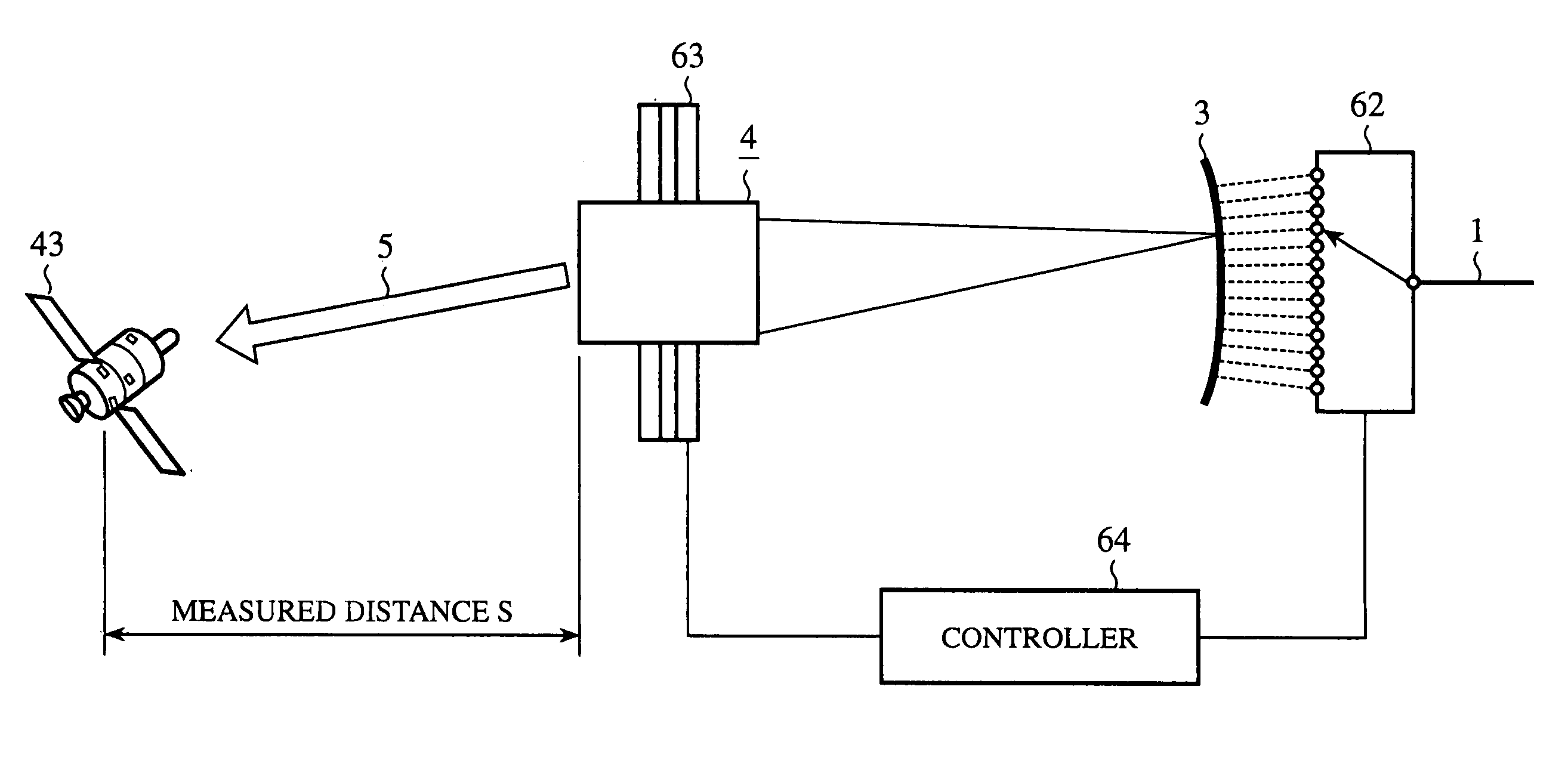
[0040]FIG. 3 is a diagram showing a configuration of an embodiment 3 of the optical antenna in accordance with the present invention. In FIG. 3, since the same reference numerals designate the same or like portions to those of FIG. 1, their description will be omitted here. The optical antenna of FIG. 3 is applied to a wind speed measuring LIDAR (Light Detection And Ranging) apparatus.

[0041] Optical transmitting and receiving sections 31 and 32 constitute an optical transmitting and receiving means for radiating outgoing laser beams toward the space, and for receiving incoming laser beams from the space. Laser light sources 33 of the optical transmitting and receiving sections 31 and 32 each emit a laser beam under the control of a controller 36. Optical path bifurcating sections 34 divide the optical fibers 1 and 2 into two branches each. Optical receivers 35 receive laser beams from the optical fibers 1 and 2, convert the laser beams into electric signals, and supply them to the ...


PUM


Abstract

An optical antenna includes an optical element mount (3) for mounting fiber ends (1a and 2a) of optical fibers (1 and 2) at different positions; and an optical transmitting and receiving system (4) for collimating, when laser beams are radiated from the fiber ends (1a and 2a), the laser beams to parallel light rays toward the space, and for focusing, when laser beams arrive from the space, the laser beams onto the fiber ends (1a and 2a) This makes it possible to set two optical transmitting and receiving directions 5 and 6 without installing complicated mechanical elements.

Description

TECHNICAL FIELD [0001] The present invention relates to an optical antenna for transmitting and receiving a laser beam to and from space. BACKGROUND ART [0002] A conventional optical antenna controls the transmitting and receiving direction of a laser beam by having a position adjuster for three-dimensionally aligning the position of an optical fiber with the imaging lens of an optical system, and a gimbal mechanism for controlling movement of a casing that accommodates the optical antenna (see, the following Relevant Reference 1). [0003] Relevant Reference 1: Japanese patent application laid-open No. 10-233738 / 1998 (see, paragraphs [0018]-[0022], and FIG. 2) With the foregoing configuration, the conventional optical antenna can control the transmitting and receiving direction of the laser beam in accordance with the position of an object to be measured even though it changes its position. However, to control the transmitting and receiving direction of the laser beam, it is necessar...

Claims


Application Information

Patent Timeline
Patent Type & Authority Applications(United States)
IPC IPC(8): G02B6/26G02B6/32G02B6/42H04B10/118
CPCG02B6/32H04B10/118G02B6/4246G02B6/4206
Inventor SUZUKI, JIROHIRANO, YOSHIHITOANDO, TOSHIYUKITAMAGAWA, YASUHISA
Owner MITSUBISHI ELECTRIC CORP
Why Eureka
Try Eureka