Reactant liquid system for facilitating the production of carbon nanostructures

a liquid system and reactant technology, applied in the direction of material nanotechnology, single-walled nanotubes, chemistry apparatus and processes, etc., can solve the problems of affecting the quality and properties of carbon nanotubes, slowed the application practicability of carbon nanostructures in products, and only small quantities of carbon nanotubes of inconsistent quality

Inactive Publication Date: 2006-01-12
CLEAN TECH INT
View PDF47 Cites 20 Cited by
  • Summary
  • Abstract
  • Description
  • Claims
  • Application Information

AI Technical Summary

Benefits of technology

[0008] The isolation of carbon atoms as conditioned carbide anions within the scope of the present invention may be accomplished by chemical reduction, chemical oxidation, reactions from acids, bases, or salts, or pyrolysis in the reactant liquid. For example, one preferred form of the invention utilizes a liquid reactant metal to chemically reduce a carbon-bearing feed material to isolate carbon atoms from the feed material and elevate the energy state of the isolated carbon atoms to form the desired conditioned carbon anions, that is, carbon anions at least at the SP3 hybrid energy state. Regardless of the particular mechanism by which the reactant liquid isolates the carbon atoms, maintaining carbon atoms that have been separated from the feed material below the surface of the reactant liquid allows the carbon atoms to remain isolated from each other and other materials with which bonds could form and allows the carbon atoms to be energized to the desired conditioned state.

Problems solved by technology

Despite the interest in carbon nanostructures and the potentially important uses for such structures, the practical application of carbon nanostructures in products has been slowed by the difficulty in manufacturing such structures.
The prior processes for producing or isolating carbon nanotubes have been found to produce only small quantities of carbon nanotubes of inconsistent quality.
These impurities incorporated in the walls of the carbon nanotubes may have a negative impact on the qualities and properties of the nanotube and may render it unsuitable for an intended purpose.
In particular, prior carbon nanostructure production techniques include no mechanism for preventing hydrogen atoms and other atoms that may be present in the carbon-bearing feed material from being incorporated into the nanocarbon structure.
Also, prior carbon nanostructure production techniques tend to allow carbon from the feed material to become incorporated into the carbon nanostructures in an unpredictable fashion outside of the desired interconnected hexagonal ring structure.
This inclusion of amorphous carbon in the resulting carbon nanostructure greatly degrades the properties and usefulness of the resulting carbon nanostructure.

Method used


Image

  • Reactant liquid system for facilitating the production of carbon nanostructures
  • Reactant liquid system for facilitating the production of carbon nanostructures
  • Reactant liquid system for facilitating the production of carbon nanostructures

Examples


Embodiment Construction

[0019] The claims at the end of this application set out novel features which the Applicant believes are characteristic of the invention. The various advantages and features of the invention together with preferred modes of use of the invention will best be understood by reference to the following description of illustrative embodiments read in conjunction with the drawings introduced above.

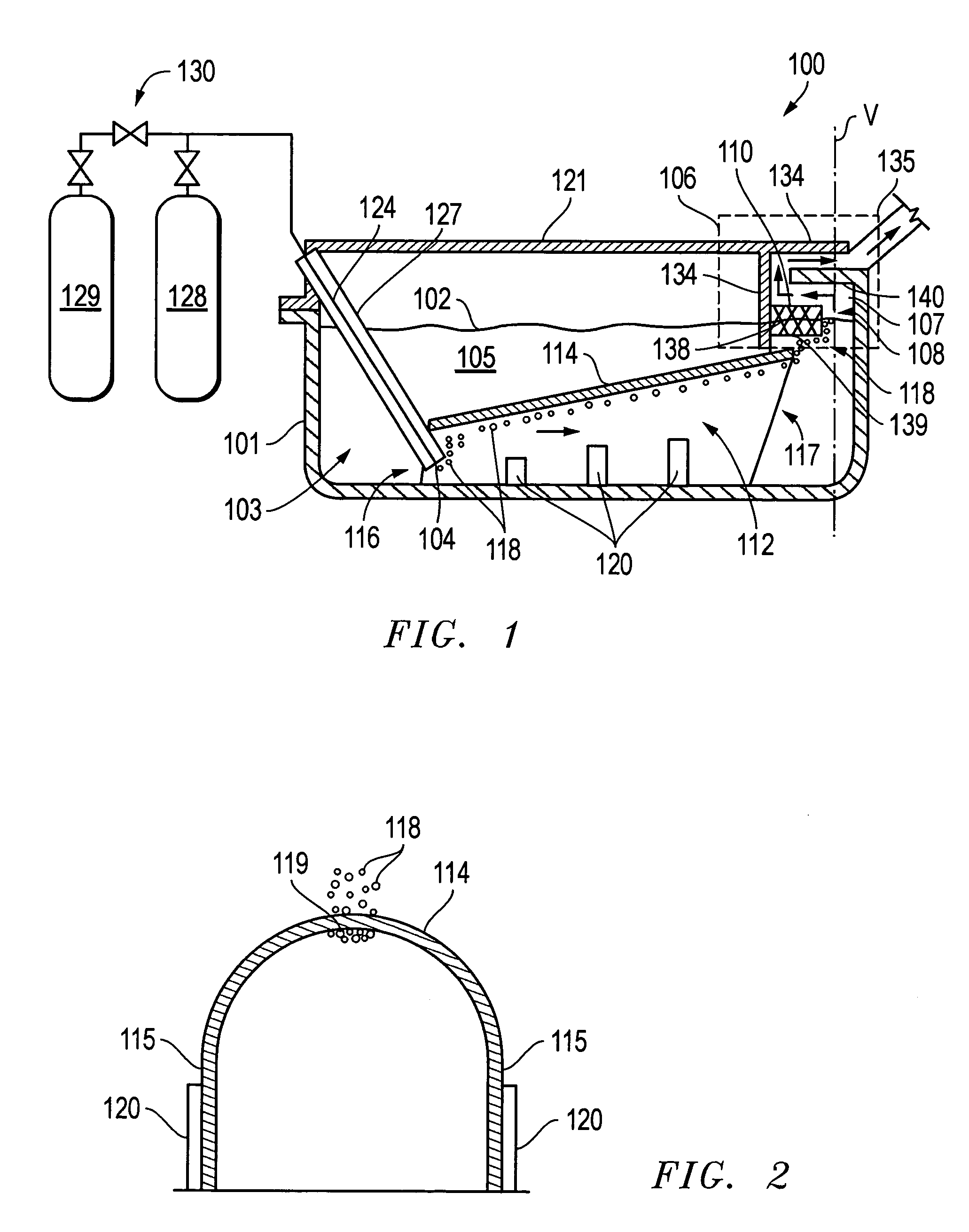
[0020] Referring to the diagrammatic representation of FIG. 1, an apparatus 100 for producing carbon nanostructures according to the present invention includes a reactant liquid vessel 101 for containing a reactant liquid 105 at a reactant liquid level 102. An injection arrangement shown generally at reference numeral 103 allows a stream of feed material to be injected into reactant liquid vessel 101 at an injection point 104 below reactant liquid level 102. Apparatus 100 further includes a collection arrangement shown generally in dashed box 106. The illustrated collection arrangement includes ...


PUM

PropertyMeasurementUnit
temperatureaaaaaaaaaa
hybrid energyaaaaaaaaaa
pressureaaaaaaaaaa

Abstract

A method includes isolating carbon atoms as conditioned carbide anions below a surface of a reactant liquid. The conditioned carbide anions are then enabled to escape from the reactant liquid to a collection area where carbon nanostructures may form. A carbon structure produced in this fashion includes at least one layer made up of hexagonally arranged carbon atoms. Each carbon atom has three covalent bonds to adjoining carbon atoms and one unbound pi electron.

Description

CROSS-REFERENCE TO RELATED APPLICATIONS [0001] This application is a continuation-in-part of U.S. patent application Ser. No. 10 / 887,695, entitled “Method and Apparatus for Producing Carbon Nanostructures,” and a continuation-in-part of U.S. patent application Ser. No. 11 / 025,717, entitled “Method and Apparatus for Preparing A Collection Surface for Use in Producing Carbon Nanostructures.” The Applicant claims the benefit of each of these applications under 35 U.S.C. § 120. The entire content of each of these applications is incorporated herein by this reference.TECHNICAL FIELD OF THE INVENTION [0002] The present invention relates to methods for manufacturing carbon nanotubes and other carbon nanostructures from a carbon-bearing feedstock. In particular, the invention relates to methods for placing carbon atoms in condition to form impurity-free carbon nanostructures. The invention also includes a particular type of carbon nanostructure. BACKGROUND OF THE INVENTION [0003] Carbon nan...

Claims


Application Information

Patent Timeline
Patent Type & Authority Applications(United States)
IPC IPC(8): C01B31/30
CPCB82Y30/00B82Y40/00C01B31/0246C01B2202/04C01B31/30C01B2202/02C01B31/0293Y10S977/842Y10S977/844C01B32/166C01B32/18C01B32/90
Inventor WAGNER, ANTHONY S.
Owner CLEAN TECH INT
Why Eureka
Try Eureka