Variable-loss transmitter and method of operation

a transmitter and variable-loss technology, applied in wireless communication, power management, sustainable buildings, etc., can solve the problems of reducing the signal-to-noise ratio, reducing the performance of the wireless communication device, and the problem is even more pronounced for mobile handsets, so as to reduce the source signal attenuation, reduce the signal attenuation, and increase the gain level

Inactive Publication Date: 2006-01-12
GE TECH DEV INC GETD
View PDF99 Cites 15 Cited by
  • Summary
  • Abstract
  • Description
  • Claims
  • Application Information

AI Technical Summary

Benefits of technology

[0007] As a benefit of this approach, the controller is able to configure the source amplifier to have a decreased signal attenuation (increased gain level) during the low power operation of the transmitter in contrast to conventional techniques which increase the source signal attenuation during low power operation. As discussed below, reduction in the source signal attenuation results in improved SNR, and ultimately, improved device performance.

Problems solved by technology

The simplicity of such an implementation, however, is achieved at the cost of reduced signal-to-noise ratio (“SNR”), particularly during low power operation.
Reduced SNR significantly diminishes the performance of the wireless communication device.
This problem is even more pronounced for mobile handsets, such as CDMA mobile handsets, which operate in low power for a substantial amount of the time.

Method used


Image

  • Variable-loss transmitter and method of operation
  • Variable-loss transmitter and method of operation
  • Variable-loss transmitter and method of operation

Examples


Embodiment Construction

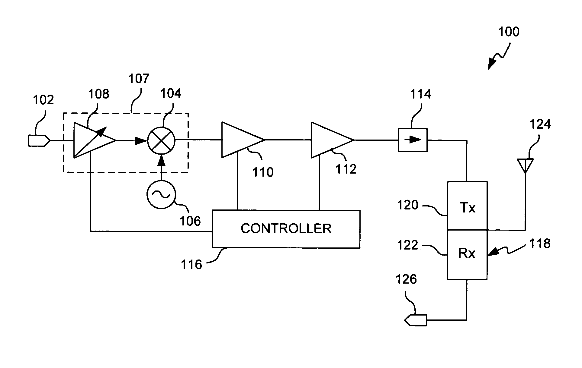
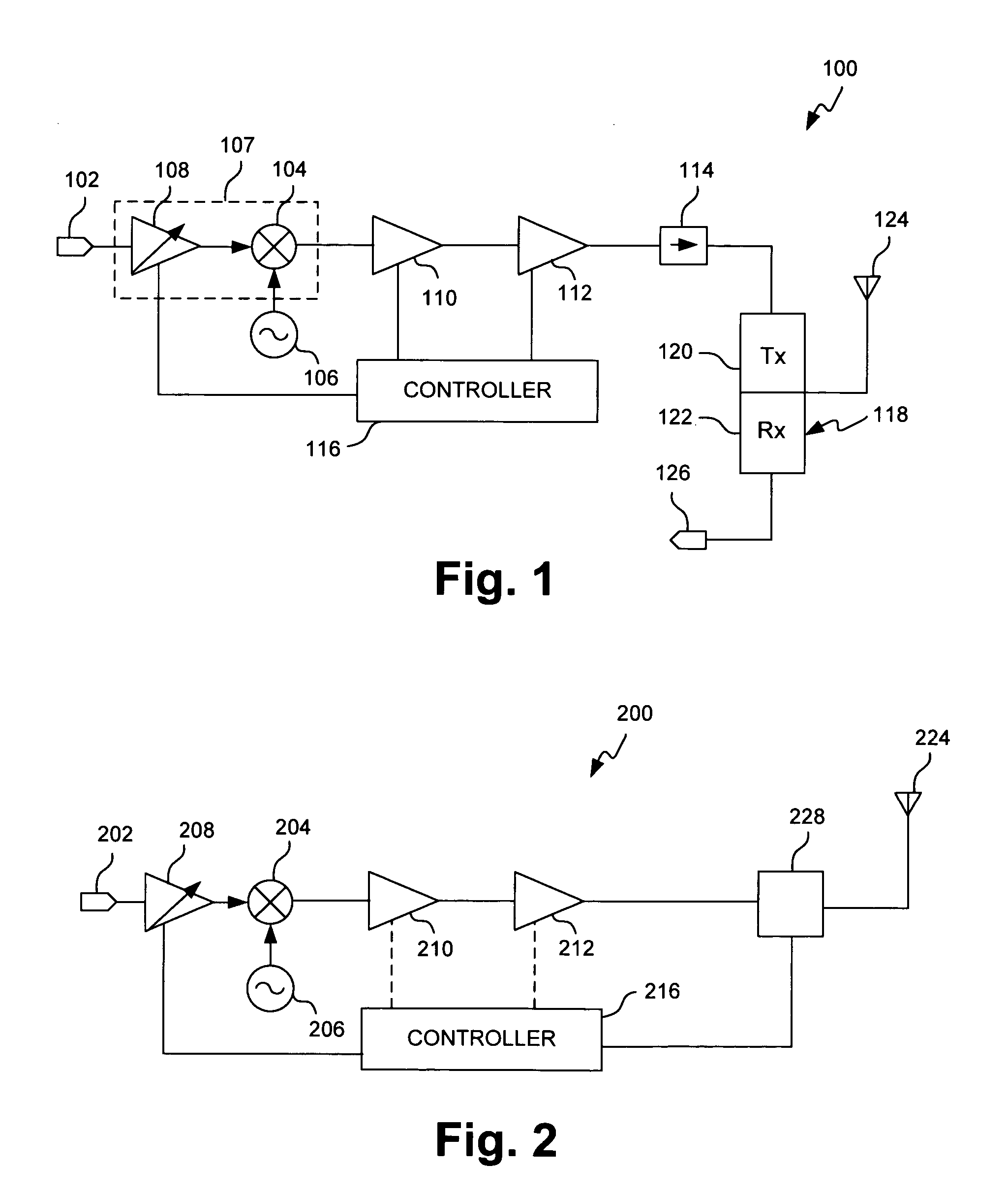
[0012] Referring first to FIG. 1, there is shown a simplified view of exemplary transceiver 100 according to one embodiment of the present invention. Transceiver 100 may, for example, be implemented in a wireless communication device, such as a mobile phone or a base station, capable of communicating RF signals in one or more frequency bands. As discussed in greater detail below, transceiver 100 achieves significantly improved SNR during low power operation.

[0013] As shown in FIG. 1, transceiver 100 comprises source amplifier 108, mixer 104, driver amplifier 110, power amplifier 112, isolator 114, duplexer 118 and antenna 124. Controller 116 controls the operation of transceiver 100 and, more particularly, the operation of source amplifier 108, driver amplifier 110 and / or power amplifier 112, as discussed below.

[0014] Although duplexer 118 includes transmits path 120 and receive path 122, the present discussion will be limited to communications associated with transmit path 120. A...


PUM


Abstract

An exemplary transceiver comprises a power amplifier configured to receive a source signal and generate an amplified output signal, an antenna coupled to the power amplifier, the antenna being configured to radiate the amplified output signal, and a controller coupled to the power amplifier. The controller is configured to control an effective gain of the power amplifier based on a power level of operation of the transmitter. A source amplifier configured to operate on the source signal prior to power amplification is also controlled by the controller. The controller configures the gain level of the source amplifier based on the power level of operation of the transmitter and the effective gain of the power amplifier to improve signal-to-noise ratio.

Description

FIELD OF THE INVENTION [0001] The present invention relates to the field of wireless communication devices. More specifically, the invention relates to RF transmitters for wireless communication devices. BACKGROUND OF THE INVENTION [0002] A typical wireless communication device, such as a mobile phone, comprises, among other things, a processor coupled to a memory and to a transceiver, each enclosed in a housing. A mobile power source, such as a battery, is coupled to and supplies power to the processor, the memory and the transceiver. A speaker and a microphone are also enclosed within the housing for transmitting and receiving, respectively, acoustic signals to and from a user of the wireless communication device. The wireless communication device communicates information by transmitting and receiving electromagnetic (“EM”) energy in the radio frequency (“RF”) band via an antenna coupled to the transceiver. [0003] During transmission, the source signal is modulated, amplified and ...

Claims


Application Information

Patent Timeline
Patent Type & Authority Applications(United States)
IPC IPC(8): H04Q7/20H04W52/52
CPCH03F1/0205H03G3/3042Y02B60/50H04W52/52H04B2001/0416
Inventor DUNN, DOUG
Owner GE TECH DEV INC GETD
Why Eureka
Try Eureka