
Lane changing assistant for motor vehicles

a technology for assistants and motor vehicles, applied in brake systems, process and machine control, instruments, etc., can solve the problem of not being able to change lanes, and achieve the effect of making the change of lanes easier for the driver

Active Publication Date: 2006-01-12
ROBERT BOSCH GMBH
View PDF8 Cites 114 Cited by
  • Summary
  • Abstract
  • Description
  • Claims
  • Application Information

AI Technical Summary

Benefits of technology

[0008] The present invention offers the advantage that changing lanes is made easier for the driver in that the lane changing assistant automatically recognizes a suitable window for a danger-free changing to the adjacent lane, and, in the light of this information, automatically determines the most favorable point time to initiate the acceleration procedure.
[0012] As a rule, known blinker switches are developed to have two stages, and in the first stage they act as a pushbutton switch without automatic holding function, while in the second stage they lock into place in a switched in state. According to one refinement of the present invention, the blinker switch may be developed in such a way that the operation of the first stage acts to switch on the directional indicator only if a lane change is actually possible. If, on the other hand, the lane change is not possible, the blinker light is switched on effectively only if a suitable window for lane change has opened. In this manner one may avoid irritating the traffic in the passing lane by the premature setting of the blinker. The lighting up of the blinker control light on the dashboard then gives the driver an additional signal that lane change is possible. The second stage of the blinker switch gives the driver the possibility of overriding this function and switching on the blinker light at once.

Problems solved by technology

When, on the other hand, the driver operates the blinker switch and thereupon the expected acceleration thrust does not occur, this indicates to the driver that a lane change is not yet possible.

Method used


Image

  • Lane changing assistant for motor vehicles
  • Lane changing assistant for motor vehicles
  • Lane changing assistant for motor vehicles

Examples


Embodiment Construction

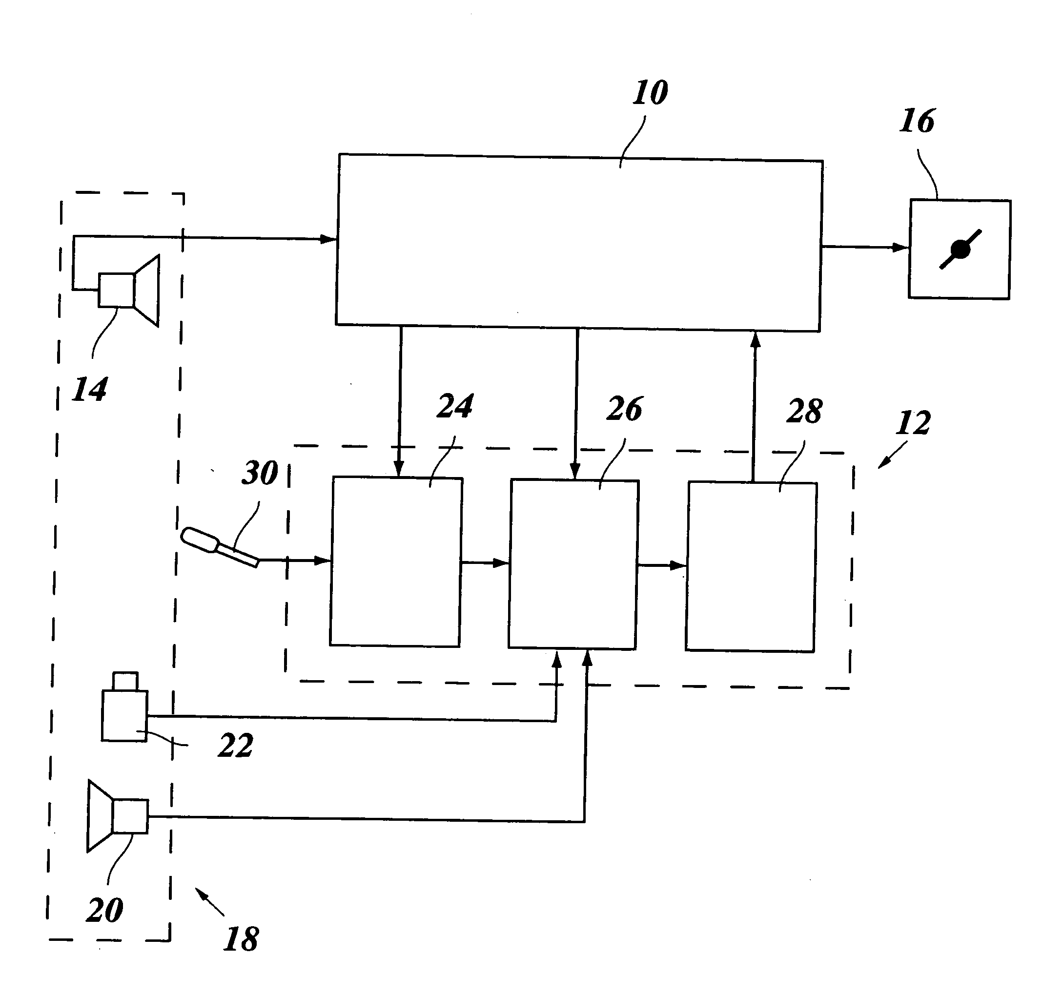
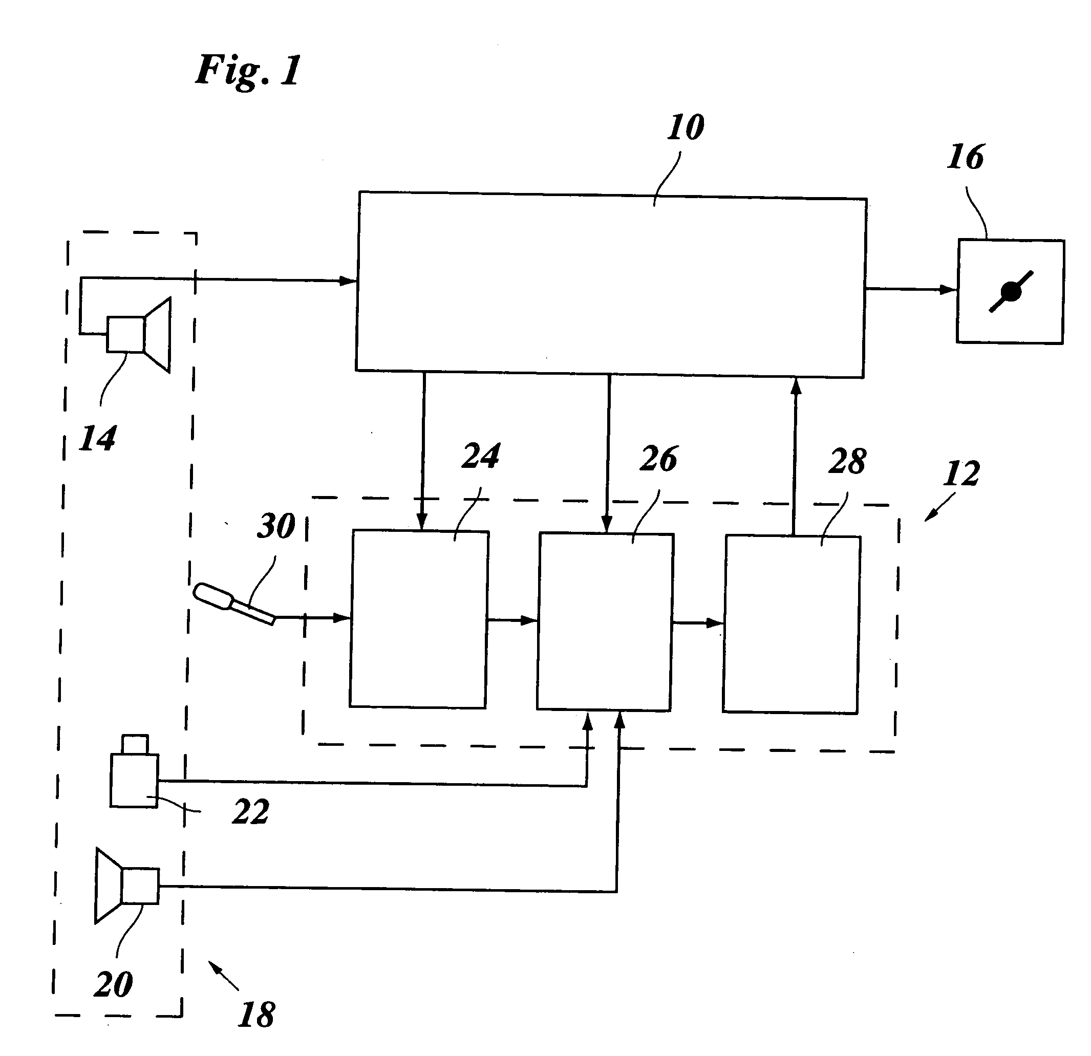
[0033] As a simplified block diagram, FIG. 1 shows a speed control system 10 for a motor vehicle, and an appertaining lane changing assistant 12. Speed control system 10 receives signals from a front radar 14 and intervenes in drive system 16, as well as in the braking system of the vehicle, if necessary, that is not shown. The functions of speed control system 10 correspond to those of a known ACC system, and are therefore not explained here in greater detail.

[0034] Front radar 14 is a part of a surroundings sensor system 18, to which there also belongs a rear-facing radar 20 and a very close range sensor 22.

[0035] Lane changing assistant 12 is represented here by three function blocks, namely, one decision device 24 to decide whether a lane changing request should be accepted, a recognition device 26 to recognize a suitable lane changing window in flowing traffic in the adjacent lane, and a computing device 28 to compute an acceleration strategy, and to output a corresponding ac...


PUM


Abstract

A lane changing assistant for motor vehicles, having a speed control system and a surroundings sensor system for recording the traffic environment including the traffic in an adjacent lane, having a decision device for deciding whether a lane changing request of the driver is to be accepted, and having a command device for issuing an acceleration command to the speed control system in the case of a lane changing request, wherein a recognition device is developed to recognize a window for swinging into the adjacent lane without danger, in the light of the data of the surroundings sensor system; and the command device is developed to compute an acceleration strategy adjusted to the window, including a point in time for the beginning of the acceleration.

Description

FIELD OF THE INVENTION [0001] The present invention relates to a lane changing assistant for motor vehicles, having a speed control system and a surroundings sensor system for recording the traffic environment including the traffic in an adjacent lane, having a decision device for deciding whether a lane changing request of the driver is to be accepted, and having a command device for issuing an acceleration command to the speed control system. BACKGROUND INFORMATION [0002] A lane changing assistant of this kind is known, for example, from German Published Patent Application No. 101 14 187, and is used in connection with a speed control system, for instance, a so-called ACC system (Adaptive Cruise Control), which is not only in a position to regulate the speed of the vehicle to a speed desired by the driver, but is also in a position to adjust the speed of one's own vehicle, if necessary, to the speed of the preceding vehicle, so that the latter is being followed at a suitable safet...

Claims


Application Information

Patent Timeline
IPC IPC(8): G06F17/10B60K31/00B60W30/14B60W30/16
CPCB60W30/143B60W2750/308B60W2550/20B60W30/16B60W2754/30B60W2554/00B60W2554/406B60W2554/80
Inventor EWERHART, FRANKGUENTHER, CLEMENSWITTIG, THOMAS
Owner ROBERT BOSCH GMBH
Learn More