Exhaust gas treatment system and utility vehicle with an exhaust gas treatment system

a technology of exhaust gas treatment system and treatment system, which is applied in the direction of machines/engines, cycles, separation processes, etc., can solve the problems of increasing the installation and arrangement of corresponding utility vehicles, and the arrangement or accommodation of these units, so as to achieve the effect of small effective external surface area, short line length, and small heat loss

Inactive Publication Date: 2006-01-19
DAIMLER AG
View PDF6 Cites 6 Cited by
  • Summary
  • Abstract
  • Description
  • Claims
  • Application Information

AI Technical Summary

Benefits of technology

[0012] The inventive arrangement of the reducing agent tank between the particle reduction unit and the nitrogen oxide reduction unit provides a space-saving and compact design of the exhaust gas treatment system with short line lengths and a comparatively small effective external surface so that heat losses can be kept small.
[0013] The exhaust gas treatment system also attenuates sounds so that under certain circumstances it is possible to dispense with a separate muffler and installation space can thus be saved.
[0014] In one embodiment of the invention, the reducing agent tank at least partially surrounds the exhaust gas duct. The reducing agent tank preferably has a recess in which the exhaust gas duct extends and which is embodied, for example, in the form of a trough. Likewise it is advantageous to provide the reducing agent tank with a cylindrical bushing so that it can be fitted onto the exhaust gas duct for mounting purposes. The abovementioned embodiments permit a particularly compact design of the exhaust gas treatment system.
[0015] In a further embodiment of the invention, the reducing agent tank has a recess for accommodating a reducing agent metering unit. Reducing agent is added to the exhaust gas by the reducing agent metering unit, preferably in predefinable quantities and at times which depend on the engine operating point, via a suitable line and a reducing agent adding device. The structural integration of the reducing agent tank and reducing agent metering unit avoids gaps and protrusions and provides for a compact design with a uniform surface to be obtained.
[0016] In still a further embodiment of the invention, the exhaust gas connecting line forms a mixing section for mixing exhaust gas with metered reducing agent. An adding point for the reducing agent is positioned as far upstream as possible on the exhaust gas duct or on a further upstream extension which can be routed into the particle reduction unit. This measure according to the invention provides for a sufficiently long mixing section for mixing and homogenizing exhaust gas and reducing agent in a space-saving fashion.

Problems solved by technology

However, as the complexity and size of exhaust gas treatment systems increase with greater demands on exhaust gas cleaning, the installation and arrangement in a corresponding utility vehicle are becoming more difficult.
Often there are difficulties with the arrangement or accommodation of these units, in particular with respect to the arrangement of other assemblies which are necessary to operate the utility vehicle, for example the fuel tank which usually also has a very large volume.

Method used


Image

  • Exhaust gas treatment system and utility vehicle with an exhaust gas treatment system
  • Exhaust gas treatment system and utility vehicle with an exhaust gas treatment system
  • Exhaust gas treatment system and utility vehicle with an exhaust gas treatment system

Examples


Embodiment Construction

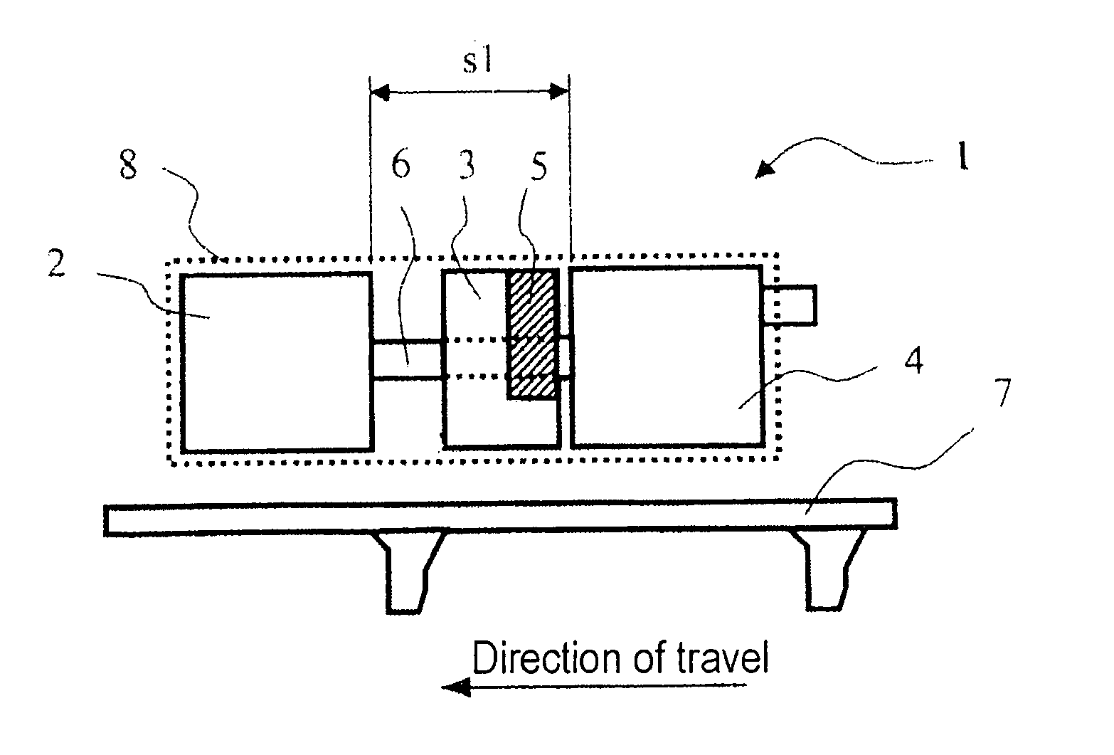
[0029] The exhaust gas treatment system 1 which is illustrated schematically in a plan view in FIG. 1 comprises, in a linear arrangement, a particle reduction unit 2, a reducing agent tank 3 and a nitrogen oxide reduction unit 4. Exhaust gas which is has been filtered for the removal of particles is directed to the nitrogen oxide reduction unit 4 from the particle reduction unit 2 via an exhaust gas connecting line 6. The exhaust gas treatment system 1 also has a reducing agent metering unit 5 for metering the reducing agent into the exhaust gas The entire exhaust gas treatment system 1 is arranged here on the right of a right-hand longitudinal frame member 7 of the utility vehicle viewed in the direction of travel, supported on a supporting structure (not illustrated) which is attached to the longitudinal frame member 7. The exhaust gas treatment system 1 may be arranged at different locations depending on the design of the vehicle. However, for reasons of stability and space an ar...


PUM


Abstract

In an exhaust gas treatment system and a utility vehicle having an exhaust gas treatment system, the exhaust gas treatment system includes a particle reduction unit, a reducing agent tank and a nitrogen oxide reduction unit of a modular design, wherein the reducing agent tank is arranged between the particle reduction unit and the nitrogen oxide reduction unit and extends around a connecting line extending between the particle reduction unit and the nitrogen oxide reduction unit, and in a utility vehicle, the associated exhaust gas treatment system is arranged within a predefined cuboid envelope volume on a support structure which is attached to a frame member of the vehicle.

Description

[0001] This is a Continuation-In-Part Application of international application PCT / EP03 / 13918 filed Dec. 09, 2003 and claiming the priority of German application 103 05 057.4 filed Feb. 07, 2003. BACKGROUND OF THE INVENTION [0002] The invention relates to an exhaust gas treatment system including a particle removing unit and a nitrogen oxide removing unit disposed in an exhaust duct of an internal combustion engine and a utility vehicle with such an exhaust gas treatment system. [0003] Patent application WO 01 / 42633 describes an exhaust gas treatment system comprising a plurality of separate units. The exhaust gas treatment system may have, for example, a particle reduction unit and a nitrogen oxide reduction unit. An SCR (=selective catalytic reduction) catalytic converter, which is supplied with urea as a selective reduction agent for the nitrogen oxide, is provided as a nitrogen oxide reduction unit. The exhaust gas treatment system described is mainly considered for use in utili...

Claims


Application Information

Patent Timeline
Patent Type & Authority Applications(United States)
IPC IPC(8): F01N3/00F01N3/10B01D53/94F01N3/023F01N3/035F01N3/20F01N13/02
CPCB01D53/9431B60K13/04F01N3/0231F01N3/035F01N3/2066F01N13/009F01N2340/04F01N2610/02F01N2610/1406Y02T10/24F01N2340/02Y02T10/12Y02A50/20
Inventor KOHLER, GERHARDLADENBURGER, WERNER
Owner DAIMLER AG
Why Eureka
Try Eureka