Pressure Management system for liquefied natural gas vehicle fuel tanks

a technology of pressure management system and fuel tank, which is applied in the direction of machines/engines, electrochemical generators, and containers discharging methods, etc., can solve the problems of increasing system pressure, and achieve the effect of increasing system pressure and decreasing system pressur

Inactive Publication Date: 2006-01-19
TW CRYOGENICS
View PDF7 Cites 13 Cited by
  • Summary
  • Abstract
  • Description
  • Claims
  • Application Information

AI Technical Summary

Benefits of technology

[0012] These needs, and others, are met by the present invention which provides a storage and delivery device for a cryogenic liquid having a vessel assembly, with an inner shell and an outer shell, and a delivery line assembly having a liquid line with a regulator, a vapor line with a check valve, and a delivery line. The vessel assembly is preferably an elongated, liquid natural gas (LNG) vessel that is positioned with the longitudinal axis in a generally horizontal plane. When the vessel assembly is filled with a cryogenic liquid, such as, but not limited to, LNG, there is a liquid space and a vapor space. The liquid line is in fluid communication with the liquid space, while the vapor line is in fluid communication with the vapor space. The liquid line includes a two-way regulator. The vapor line includes a check valve. Down stream of both the two-way regulator and the check valve, the liquid line and the vapor lines are coupled at a T-joint to form the delivery line. The delivery line is further coupled to a use device, such as, but not limited to, a vaporizer or an engine. The regulator is structured to close when the pressure in the vessel reaches, or exceeds, a predetermined amount. The check valve prevents vapor flow into the vessel assembly from downstream, and is structured to open when a predetermined pressure difference exists between the vapor space and the delivery line. That is, the check valve does not simply open at a set pressure in the vapor space. As the pressure in the vessel assembly increases due t

Problems solved by technology

During storage of the cryogenic liquid, heat will penetrate the vessel and caus

Method used


Image

  • Pressure Management system for liquefied natural gas vehicle fuel tanks
  • Pressure Management system for liquefied natural gas vehicle fuel tanks

Examples


Embodiment Construction

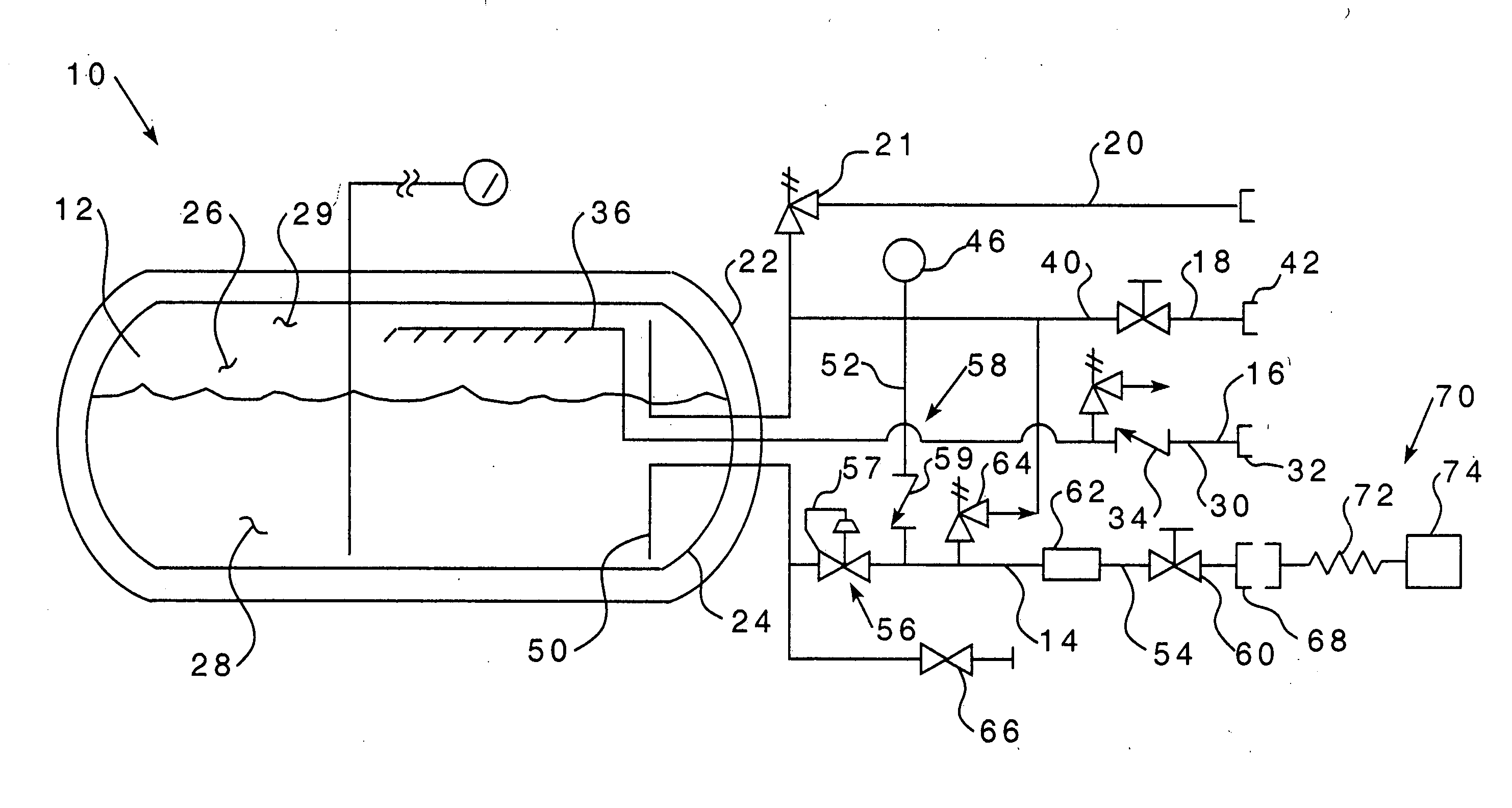
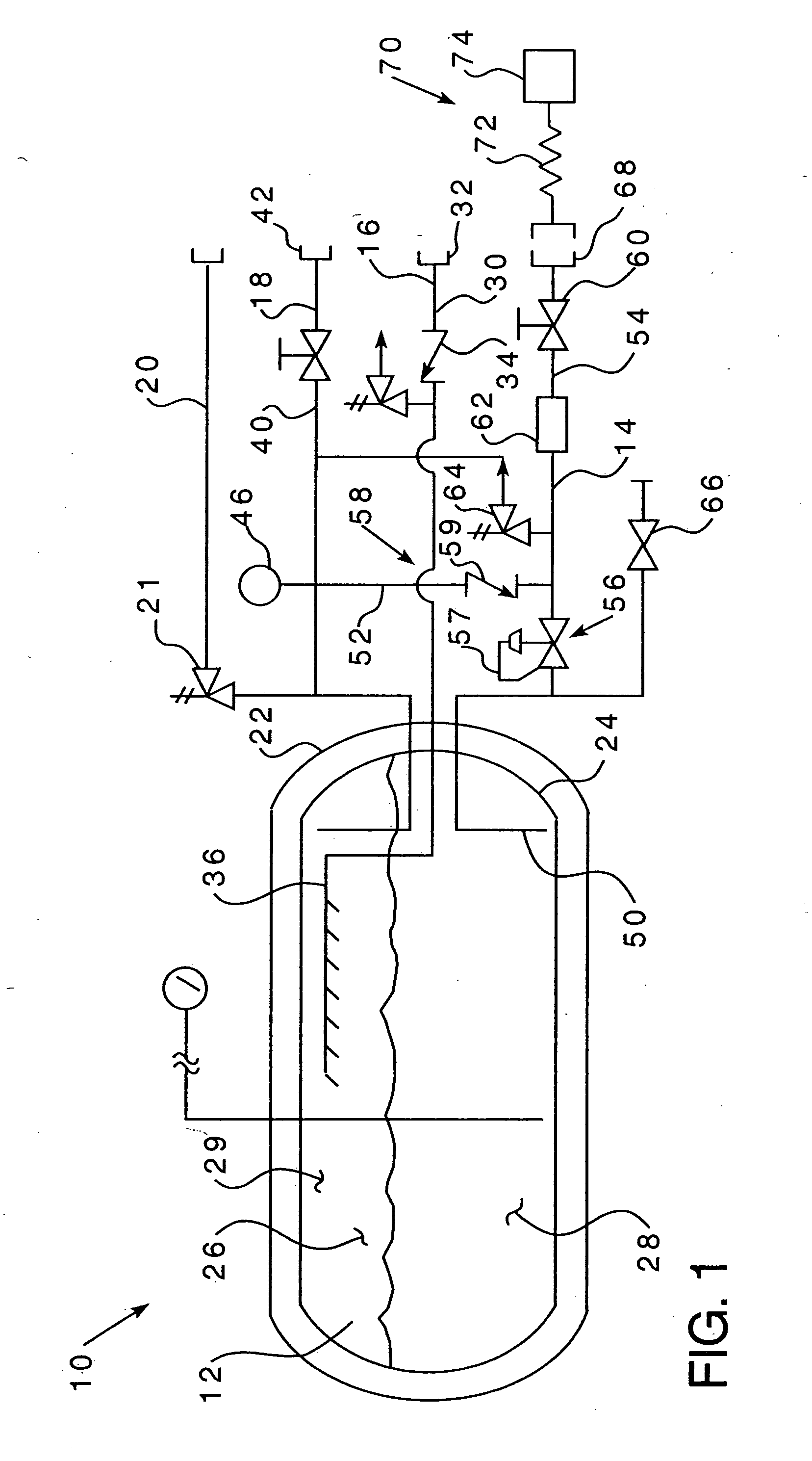
[0016] As shown in FIG. 1, a storage and delivery device 10 for a cryogenic liquid having a vessel assembly 12, a delivery line assembly 14, a fill line assembly 16, a vent line assembly 18, and an emergency vent line 20. The vessel assembly 12 includes a first, outer vessel shell 22 and a second, inner vessel shell 24. The inner vessel shell 24 defines a storage space 26 for the cryogenic liquid. Within the storage space 26 is a liquid space 28 and a vapor space 29. Between the first, outer vessel shell 22 and the second, inner vessel shell 24 is, preferably, a vacuum that acts as an insulating layer.

[0017] The fill line assembly 16 is structured to deliver a cryogenic fluid into the storage space 26. The fill line assembly 16 includes a fill line 30, a coupling device 32, a check valve 34 structured to prevent back flow out of the fill line 30 and a spray device 36. The fill line 30 extends from a point outside of the vessel assembly 12 to a point inside the storage space 26. The...


PUM


Abstract

A storage and delivery device for a cryogenic liquid that includes a vessel assembly and a delivery line assembly. The vessel assembly has a liquid space and a vapor space. The delivery line assembly has a liquid line, a vapor line, and a delivery line. The liquid line is in fluid communication with the liquid space. The vapor line is in fluid communication with the vapor space. The liquid line has a flow control device located thereon and structured to control the flow of fluid through the liquid line. The liquid line flow control device is structured to close the liquid line when the vessel assembly is at a predetermined pressure.

Description

CROSS REFERENCE TO RELATED APPLICATION [0001] This application claims priority under 35 U.S.C. §119(e) to U.S. Provisional Patent Application Ser. No. 60 / 506,339, filed Sep. 26, 2003, entitled PRESSURE MANAGEMENT SYSTEM FOR LIQUEFIED NATURAL GAS VEHICLE FUEL VESSELS.BACKGROUND OF THE INVENTION [0002] 1. Field of the Invention [0003] This invention relates to a cryogenic fluid storage system and, more specifically, to a cryogenic fluid storage system having a check valve on the vapor line at a location between the vapor space and the use device. [0004] 2. Background Information [0005] Cryogenic liquids, such as liquid natural gas (LNG), nitrogen, oxygen, CO2, hydrogen and the like, are substances that normally exist as gasses, but are liquids at cold temperatures. Special vessels and systems must be used to store and transfer cryogenic liquids because of difficulty in maintaining the extremely cold temperatures. Such vessels typically include a double walled vessel having a vacuum in...

Claims


Application Information

Patent Timeline
IPC IPC(8): F17C7/04F17C7/02F17C9/02F16KF17C13/02
CPCF17C13/025F17C2270/0184F17C2203/0391F17C2203/0629F17C2205/0332F17C2205/0335F17C2221/033F17C2223/0161F17C2223/033F17C2223/045F17C2223/047F17C2225/0161F17C2225/033F17C2225/044F17C2250/0636F17C2250/072F17C2265/031F17C2270/0168F17C2201/0109
Inventor OLDHAM, ROBERT W.OLDHAM, MARK B.
Owner TW CRYOGENICS
Why Eureka
Try Eureka