System for refrigerant charging with constant volume tank

a technology of constant volume and charging system, which is applied in the direction of lighting and heating apparatus, instruments, and containers. it can solve the problems of reducing affecting the operation of the refrigeration system, and affecting the efficiency of the refrigeration system

Active Publication Date: 2006-01-19
SPX CORP
View PDF11 Cites 61 Cited by
  • Summary
  • Abstract
  • Description
  • Claims
  • Application Information

AI Technical Summary

Benefits of technology

[0007] Described is a system for charging a refrigeration system with refrigerant. The charging system includes a refrigerant source, a storage vessel, input and output lines, and a device for detecting mass of refrigerant within the storage vessel. The input line fluidly connects the refrigerant source to the storage vessel, and the output line extends from the storage vessel and is adapted

Problems solved by technology

Most refrigeration systems are not 100% free of leaks.
Therefore, loss of refrigerant in a refrigeration system over time typically reduces the efficiency of the refrigeration system.
Also, if the amount of refrigerant in the refrigeration system drops to a certain level, the refrigeration system may cease to operate and/or be damaged.
Since the refrigeration system is designed to operate with a specific amount of refrigerant, too little or too much refrigerant can reduce the effectiveness of the recharging operation.
There are, however

Method used


Image

  • System for refrigerant charging with constant volume tank
  • System for refrigerant charging with constant volume tank
  • System for refrigerant charging with constant volume tank

Examples


Embodiment Construction

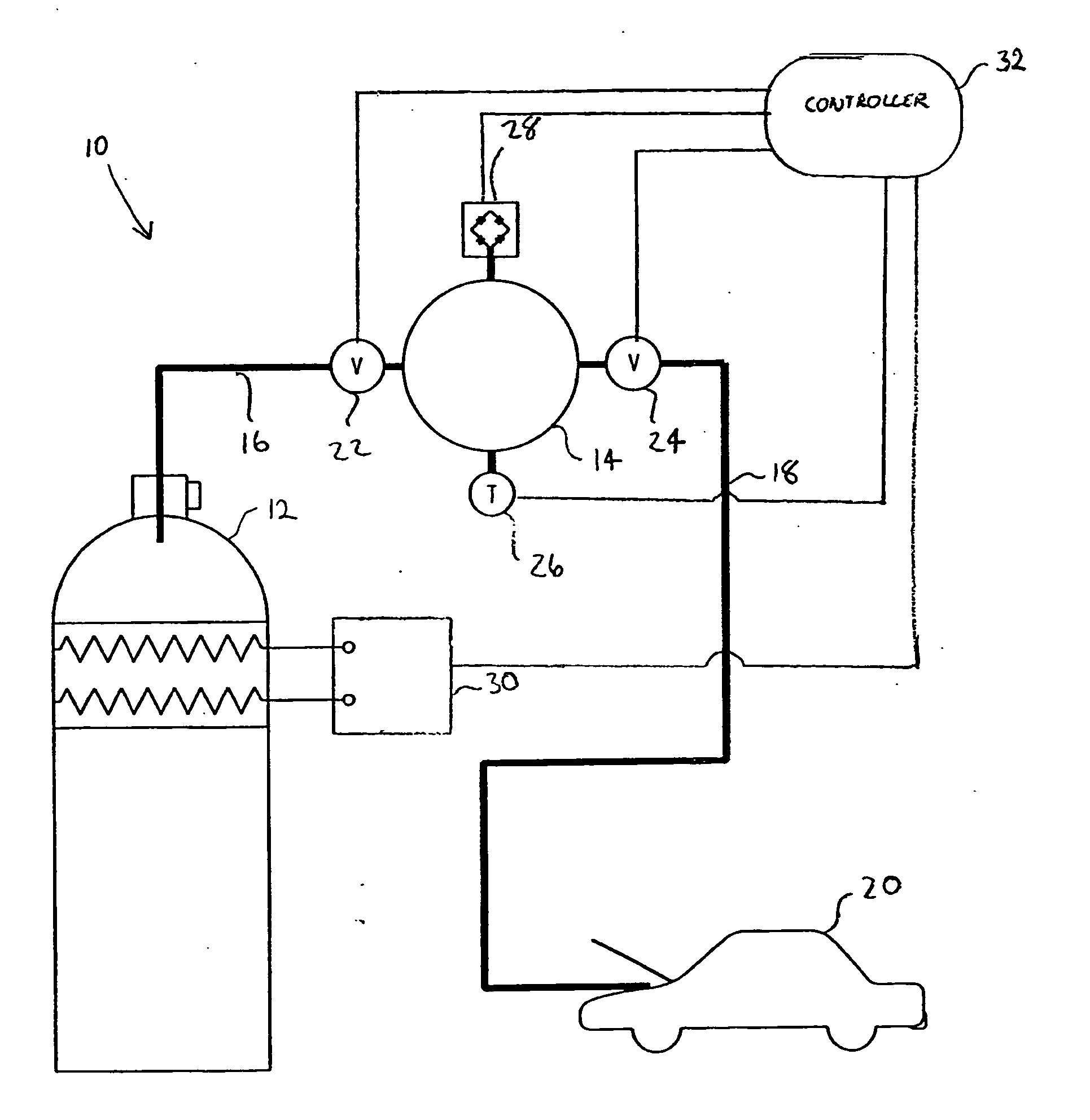
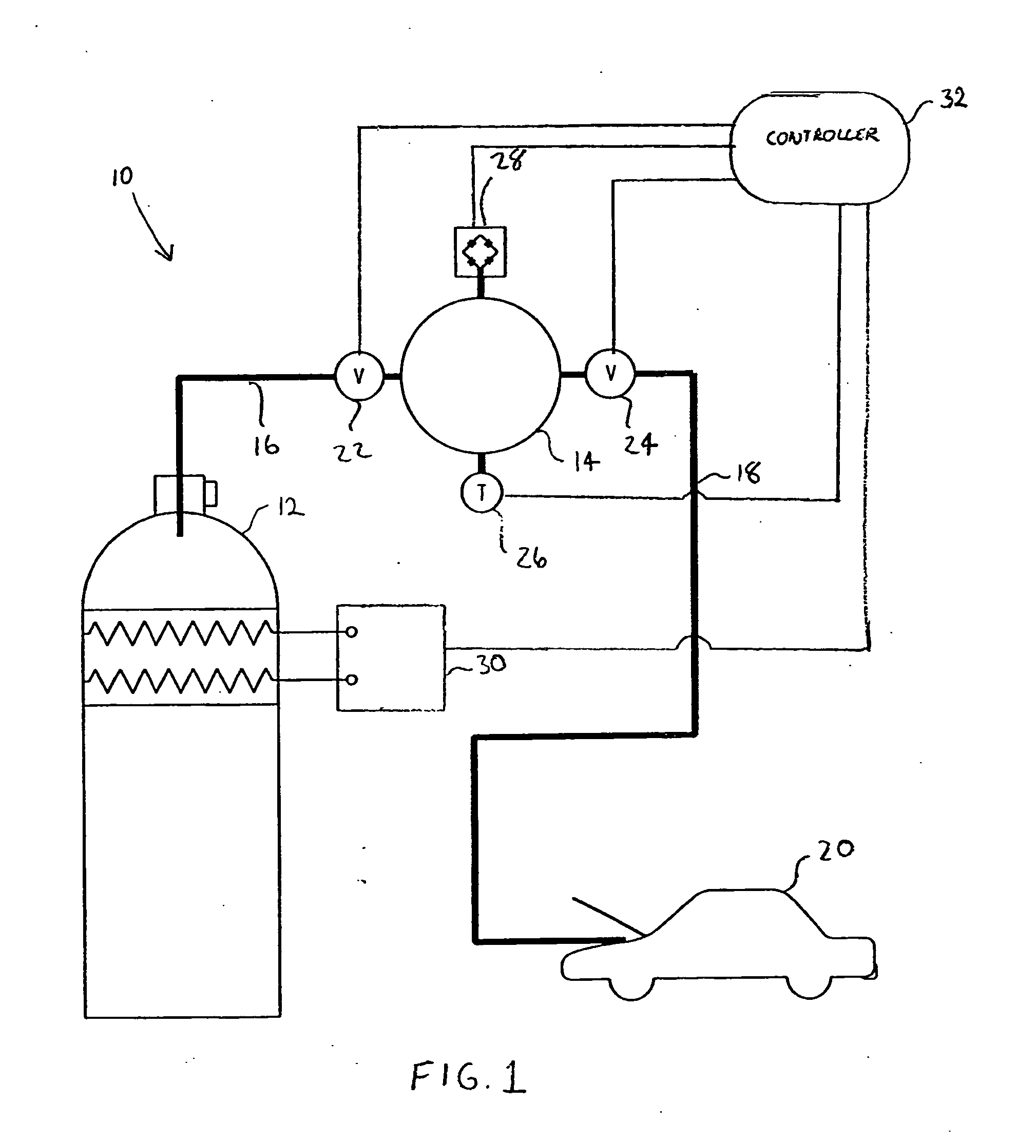
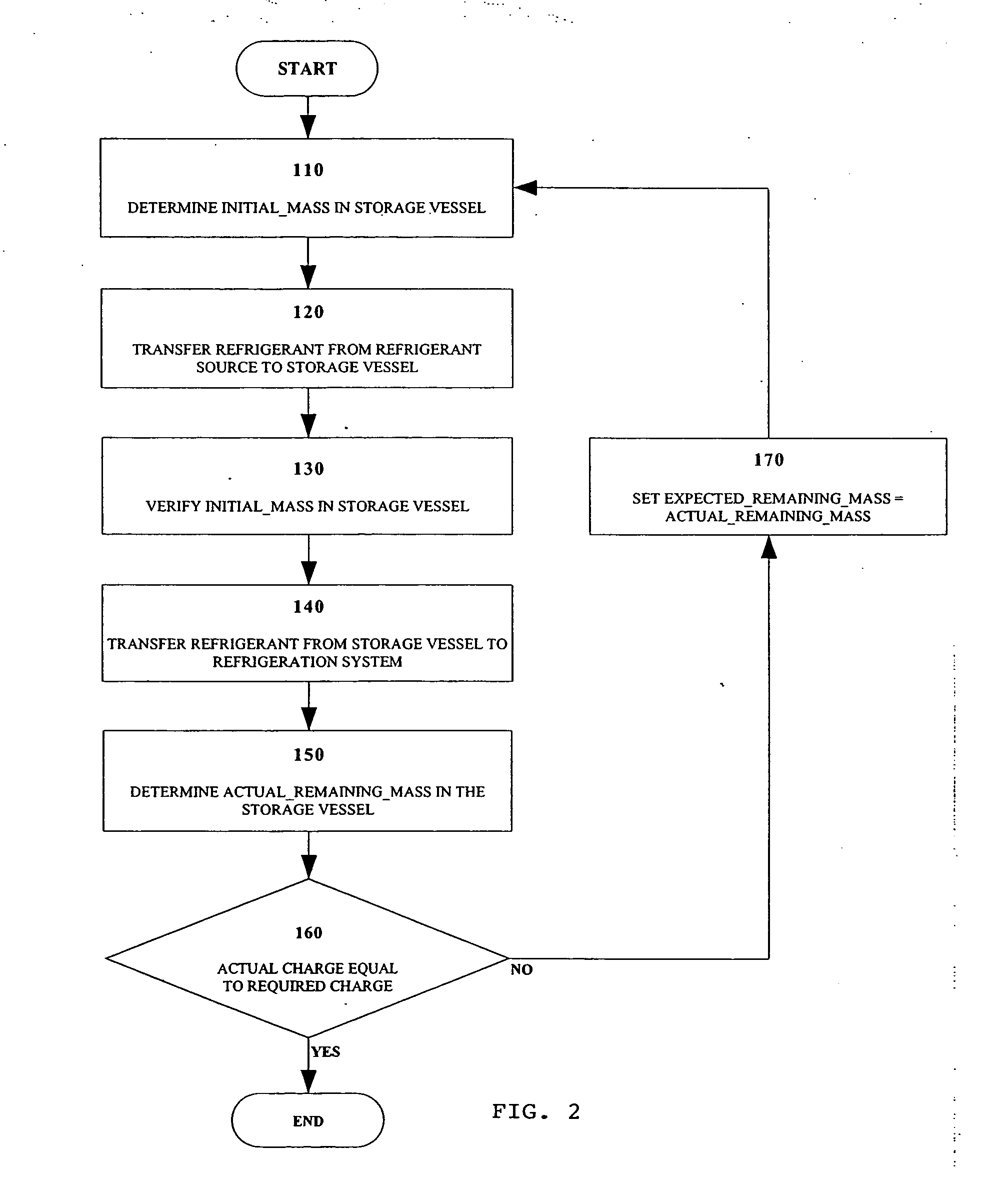
[0014] An example of a refrigerant charging system 10 according to the disclosure is illustrated in FIG. 1. The refrigerant charging system includes a refrigerant source 12, a storage vessel 14, an input line 16, and an output line 18. The input line 16 fluidly connects the refrigerant source 12 to the storage vessel 14, and the input line 16 includes an input control valve 22 for allowing refrigerant to flow to / from the input line 16 from / to the storage vessel 14. The output line 18 fluidly connects the storage vessel 14 to a refrigeration system (not shown) to be charged of a vehicle 20, and the output line 18 includes an output control valve 24 for allowing refrigerant to flow to / from the storage vessel 18 from / to the refrigeration system of the vehicle 20.

[0015] The storage vessel 14 can also include a temperature sensor 26 and a pressure sensor 28 for measuring the temperature and pressure of the refrigerant within the storage vessel. The use of a temperature and pressure sens...


PUM


Abstract

A refrigerant charging system for charging a refrigeration system with refrigerant includes a refrigerant source, a storage vessel, input and output lines, and a device for detecting mass of refrigerant within the storage vessel. The input line fluidly connects the refrigerant source to the storage vessel, and the output line extends from the storage vessel and is adapted to connect to the refrigeration system. The system also includes an input control valve disposed between the storage vessel and the refrigerant source, and an output control valve disposed between the storage vessel and the refrigeration system. A heater is connected to the refrigerant source for raising the temperature of refrigerant within the refrigerant source. A method of charging a refrigeration system is also disclosed. The system and method are useful to charging the refrigerant system of an automotive vehicle, among others.

Description

TECHNICAL FIELD [0001] The disclosure relates generally to refrigerant charging systems and, more specifically, to a high precision refrigerant charging system using a constant volume tank. BACKGROUND ART [0002] Most refrigeration systems are not 100% free of leaks. Thus, the amount (or mass) of refrigerant within the refrigeration system decreases over time. Refrigeration systems, however, are designed to operate with a specific amount of refrigerant. Therefore, loss of refrigerant in a refrigeration system over time typically reduces the efficiency of the refrigeration system. Also, if the amount of refrigerant in the refrigeration system drops to a certain level, the refrigeration system may cease to operate and / or be damaged. For these reasons, a common maintenance operation for a refrigeration system is to recharge the refrigerant within the refrigeration system. [0003] The recharging operation typically involves flushing the refrigeration system of any remaining refrigerant an...

Claims


Application Information

Patent Timeline
IPC IPC(8): F25B45/00F17C13/02G01G13/06
CPCB60H1/00585F25B45/00F25B2309/06F25B2500/19F25B2345/007F25B2400/01F25B2400/08F25B2345/001
Inventor SUHARNO, ANWARPFEFFERLE, DEAN P.GOVEKAR, CRAIG F.MELDAHL, KENNETH R.MOLLER, LARRY G.
Owner SPX CORP
Why Eureka
Try Eureka