Replaceable sleeve insert for a choke assembly

a technology of a choke assembly and a replacement sleeve, which is applied in the direction of valve operating means/releasing devices, functional valve types, transportation and packaging, etc., can solve the problems of bringing sand and other debris which erode the interior of the choke assembly, requiring replacement of the entire bonnet, and affecting the tubular projection

Active Publication Date: 2006-01-19
MI
View PDF8 Cites 30 Cited by
  • Summary
  • Abstract
  • Description
  • Claims
  • Application Information

AI Technical Summary

Benefits of technology

[0005] The claimed replaceable sleeve insert includes a tubular member with at least one attachment member extending from a first end. The tubular member has an outer diameter sufficient to fit within the upper body section of the choke assembly and an inner diameter providing sufficient clearance for coaxial linear displacement of a slidable shuttle assembly. The attachment member, or me

Problems solved by technology

During such drilling, and particularly during stimulation, high pressure gases and drilling fluids may be propelled through the choke assembly, bringing sand and other debris which erode the interior of the choke assembly.
Due to the high velocities of the flow through the choke assembly, sand and other debris that are carried with the flow quickly erode the interior of the upper body secti

Method used


Image

  • Replaceable sleeve insert for a choke assembly
  • Replaceable sleeve insert for a choke assembly
  • Replaceable sleeve insert for a choke assembly

Examples


Embodiment Construction

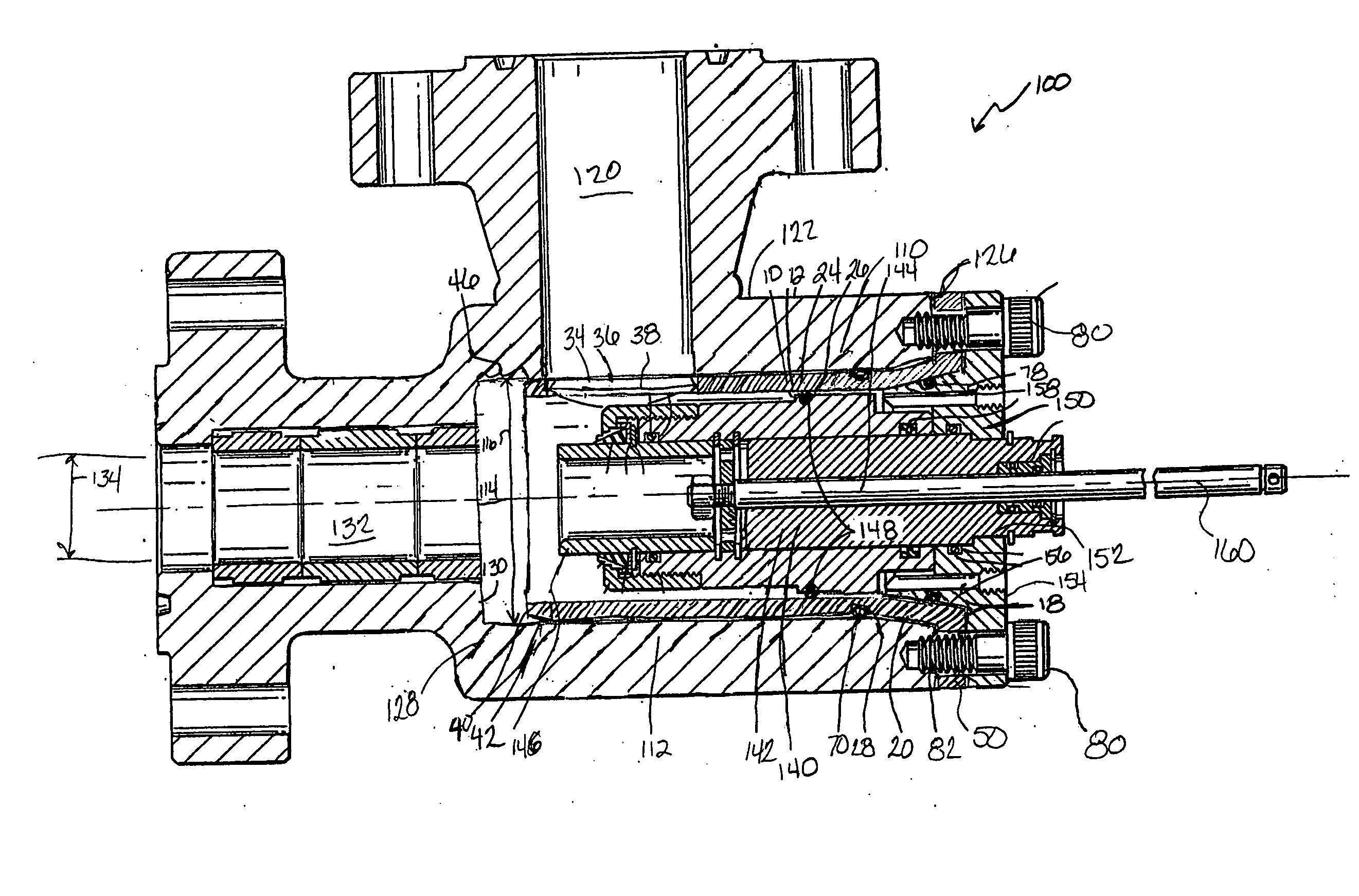
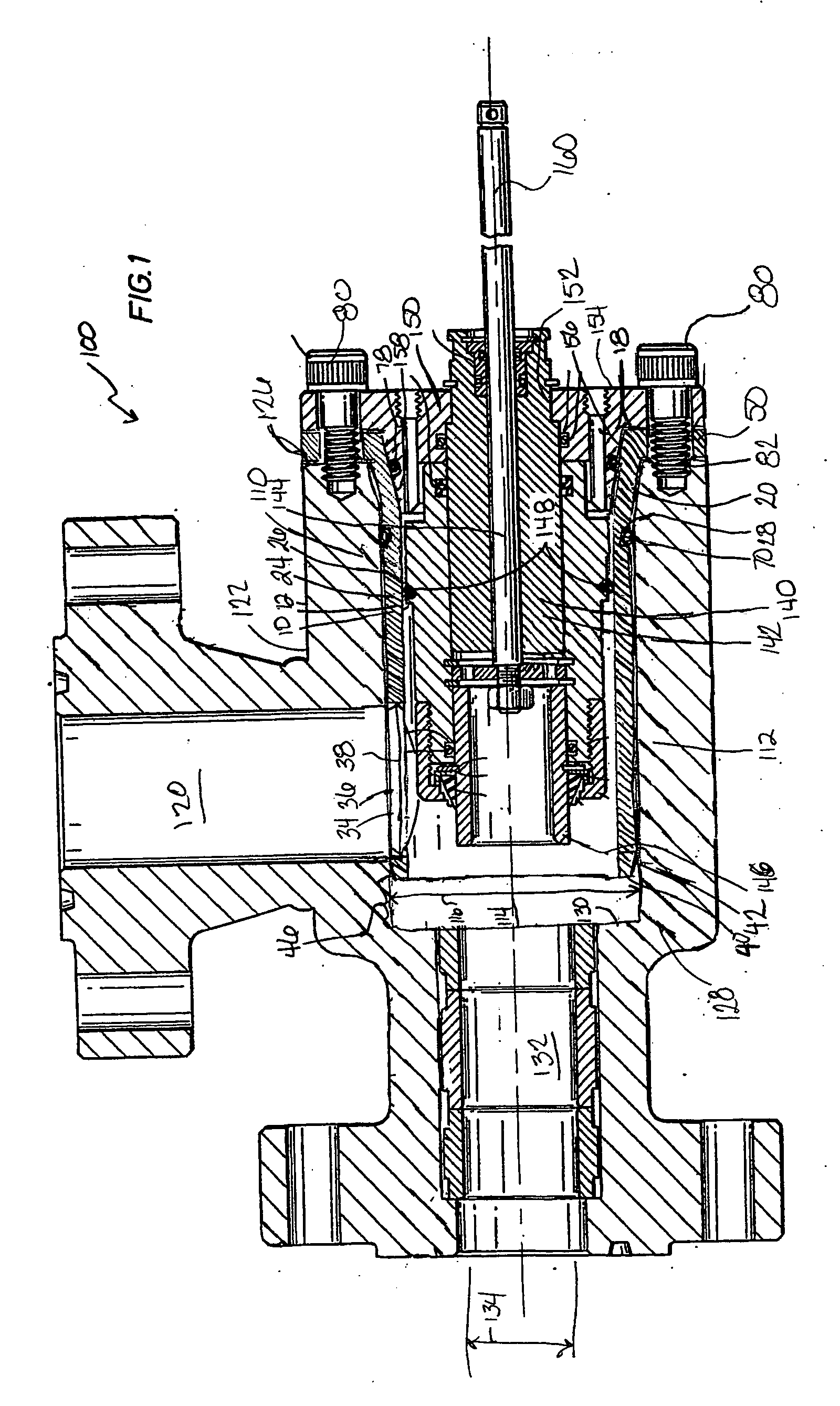
[0015] Referring to FIG. 1, a replaceable sleeve insert 10 is depicted within a choke assembly 100. The choke assembly 100 includes a choke body 110, a shuttle subassembly 140, and a bonnet 150.

[0016] The choke body 110 includes an upper body section 112, a side inlet channel 120, and an end discharge channel 132. An upper body orifice 114 extends through the length of the upper body section 112. The end discharge channel 132 adjoins upper body orifice 114 at an upper body second end 128 in coaxial alignment about a center axis 160. The end discharge channel 132 has a discharge diameter 134, which may be smaller than the upper body orifice diameter 116, thereby forming a shoulder 130 at the upper body second end 128. When present, a trim device (not shown) and valve seat (not shown) may be seated on the shoulder 130. The side inlet channel 120 feeds into a side 122 of the upper body orifice 114 between an upper body first end 126 and the upper body second end 128.

[0017] The bonnet...


PUM


Abstract

A replaceable sleeve insert for a choke assembly is disclosed, wherein the replaceable sleeve insert has a tubular member coaxially and sealingly retained within an upper body section of the choke assembly. The tubular member is also sealed against the bonnet. The tubular member has an inner diameter sufficient to accommodate coaxial linear displacement of a shuttle assembly and an outer diameter sufficient to fit within an upper body orifice in the upper body section. At least one attachment member outwardly extends from the tubular member and is retained between the upper body section and the bonnet. The tubular member has an opening in the sleeve wall to provide fluid communication from the choke inlet to the interior of the tubular member. A method of assembling a choke with a replaceable sleeve insert is also described.

Description

BACKGROUND OF INVENTION [0001] Choke assemblies are used to help regulate the pressure within a well as it is being drilled and stimulated. During such drilling, and particularly during stimulation, high pressure gases and drilling fluids may be propelled through the choke assembly, bringing sand and other debris which erode the interior of the choke assembly. [0002] Typically, choke assemblies have a side inlet channel that feeds fluid into an upper body section of the choke. Within the upper body section, the flow is redirected through an upper body orifice to an end discharge channel. A shuttle assembly is retained by a bonnet located at the end of the upper body section opposite the end discharge channel. The shuttle assembly has a shuttle that may be selectively positioned to regulate the pressure of the flow through the upper body orifice. The selective positioning includes a seated position in which the flow is stopped prior to entering the end discharge channel. [0003] Due t...

Claims


Application Information

Patent Timeline
IPC IPC(8): F16L58/04
CPCF16L55/165F16K47/08Y10T137/7668Y10T137/7036
Inventor SUTER, ROGERALAN, BURKHARD
Owner MI
Why Eureka
Try Eureka