

Exhaust system of a turbo-charged engine
a turbo-charged engine and exhaust system technology, which is applied in the direction of combustion engines, machines/engines, gas passages, etc., can solve the problems of low exhaust back pressure required to the exhaust system of the turbo-charged engine, high engine exhaust back pressure, and gas flow noise at the throttled inlet, so as to reduce the volume of the muffler, reduce the noise of the gas flow, and reduce the effect of exhaust pressur
- Summary
- Abstract
- Description
- Claims
- Application Information
AI Technical Summary
Benefits of technology
Problems solved by technology
Method used
Image

Examples
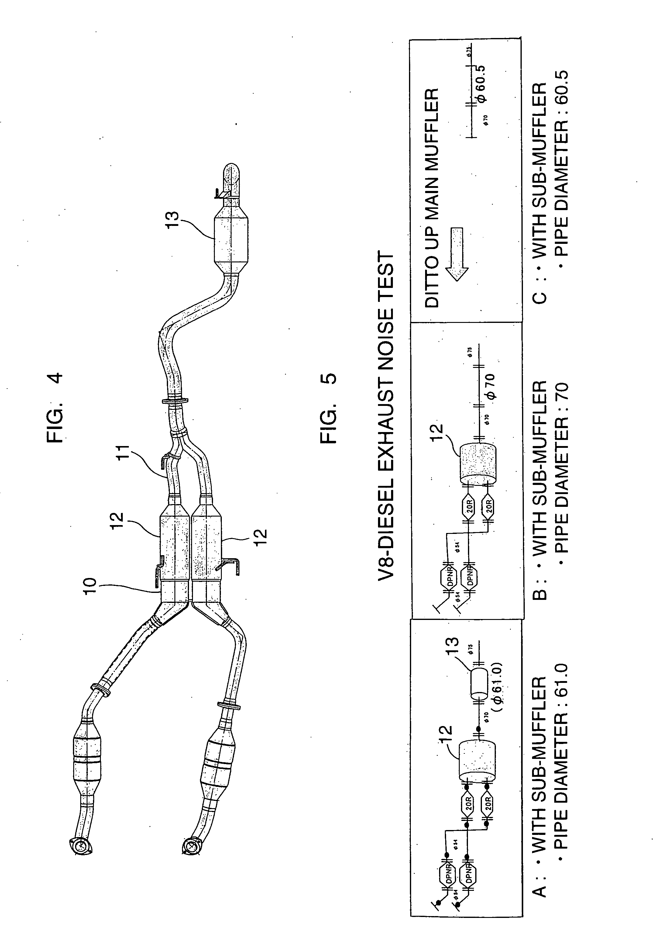
case b
[0058] a case having no subsidiary muffler (no rear muffler 13) and the diameter of the exhaust pipe was 70 mm.
case c
[0059] a case having no subsidiary muffler (no rear muffler 13) and the diameter of the exhaust pipe was 60.5 mm.
[0060] As shown in FIG. 6, in acceleration, a higher exhaust noise decreasing effect was obtained in case A (where the subsidiary muffler was provided and the pipe diameter was 61 mm) than in case C (where no subsidiary muffler was provided and the pipe diameter was 60.5 mm), and a higher exhaust noise decreasing effect was obtained in case B (where no subsidiary muffler was provided and the pipe diameter was 70 mm) than in case A (where the subsidiary muffler was provided and the pipe diameter was 61 mm). It can be understood from FIG. 6 that, in acceleration, the gas flow noise was predominant, and the noise was smaller in case A having the subsidiary muffler than in case C having no subsidiary muffler. Further, it can be understood that when the pipe diameter was large (that is, when the pipe was not throttled), the exhaust noise decreasing effect became high.
[0061] A...
PUM
 Abstract
Description
Claims
Application Information