Automated laser cutting of optical lenses

a laser cutting and optical lens technology, applied in the field of optical lens manufacturing, can solve the problems of different types of lens blanks, time-consuming process, and individual handling of lenses, and achieve the effect of enhancing the carrying of dyes or tints

Inactive Publication Date: 2006-01-19
MEANDRE
View PDF48 Cites 36 Cited by
  • Summary
  • Abstract
  • Description
  • Claims
  • Application Information

AI Technical Summary

Benefits of technology

[0012] A further enhancement of the invention provides for minor adjustment of the angle of incidence between the laser cutter and the target blank. A further enhancement of the invention provides for a “rimless” lens having a frame-shaped edge cut from a single monolithic piece of blank or feedstock material. Such shaping of th...

Problems solved by technology

The manufacture of eyeglass lenses is a time-consuming, multi-step process which generally includes the measuring of a patient's condition to derive a prescription for each eye, the measuring or tracing of the size and shape of the desired eyeglass frame, the selection of a lens blank for each eye which will accommodate the prescription for that eye and the frame, measuring or otherwise determining the optical parameters of each blank such as its power and for cylindrical lenses, its optical axis orientation, and blocking or otherwise properly orienting each lens blank according to its optical parameters and the prescription parameters in a machine or number of machines which can further process the blank into the final lens.
A difference in even one parameter may result in a different type of lens blank.
This is a time-consuming process ...

Method used


Image

  • Automated laser cutting of optical lenses
  • Automated laser cutting of optical lenses
  • Automated laser cutting of optical lenses

Examples


Embodiment Construction

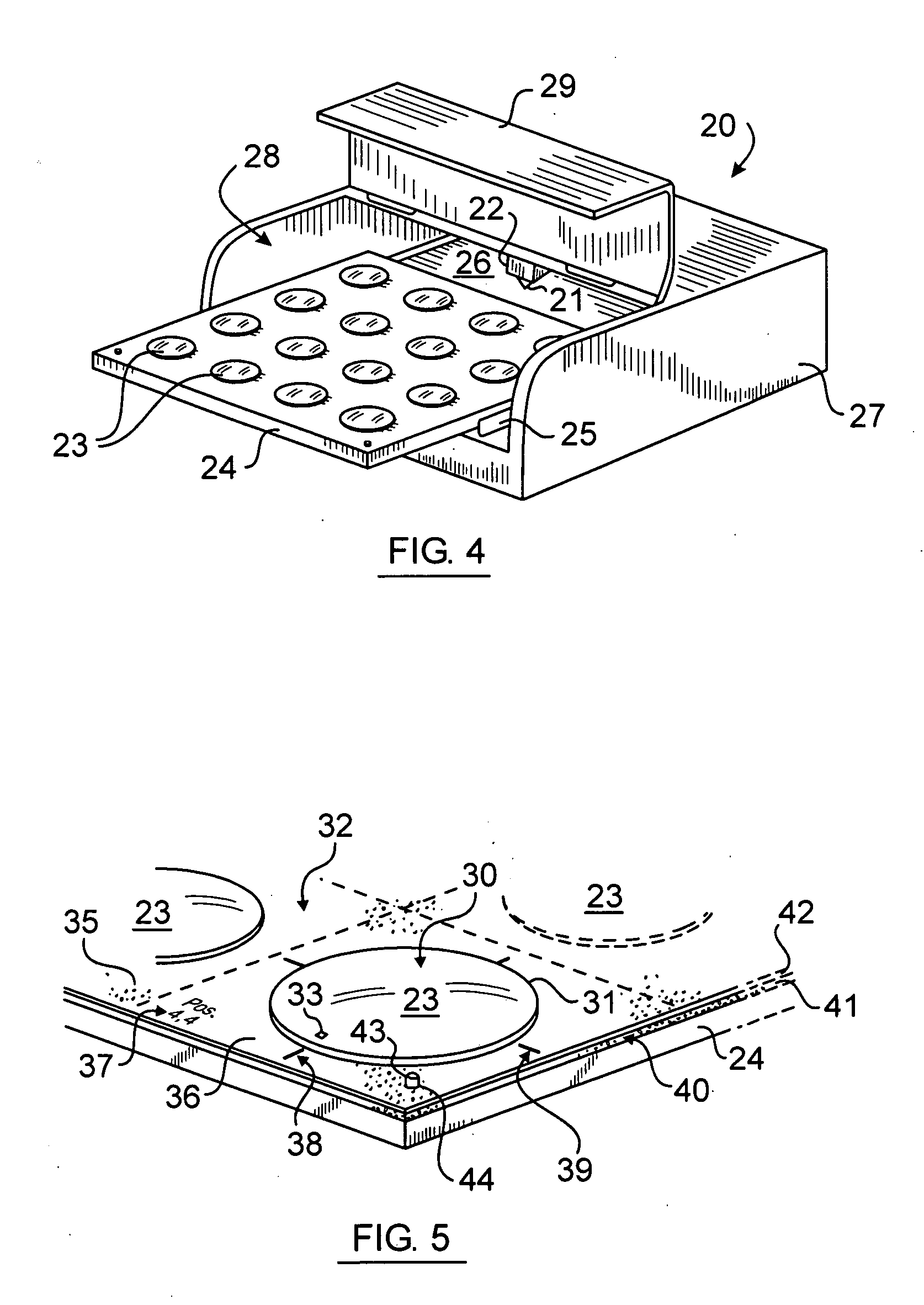
[0032] Referring now to the drawings, there is shown in FIG. 4 a laser-based optical lens blank edging device 20 having a horizontally translatable cutting laser 21 mounted upon an XY movable carriage 22 and oriented to emit a cutting beam for edging a plurality of lens blanks 23 temporarily secured upon a holder or bed 24 slidingly mounted to a drawer mechanism 25 for extraction from the internal cavity 26 of the device housing 27 through an opening 28 which is closed by a hinged lid 29 during operation. The device can be adapted from existing flatbed-style laser engravers such as disclosed in Garnier et al. U.S. Pat. No. 4,985,780 incorporated herein by this reference. A preferred laser engraver is the VENUS 35 brand engraver, commercially available from GCC USA company of Walnut, Calif.

[0033] Referring now to FIG. 5, there is shown a right / front corner portion of the bed 24 carrying a plurality of lens blanks 23. Each lens blank 23 is generally domed shape having a convex uppe...


PUM

PropertyMeasurementUnit
Angleaaaaaaaaaa
Angleaaaaaaaaaa
Angleaaaaaaaaaa

Abstract

A laser engraving device is adapted to process a plurality of lens blanks in a single processing run. The lens blanks are cut or edged serially where the laser cutter path for each blank is calculated by software which interprets lens blank optical parameters, prescription parameters and frame trace parameters, all of which can vary for each blank being edged. Minor adjustment of the angle of incidence between the laser cutter and the target blank is accomplished by a tiltable blank holder. More aesthetically appealing “rimless” lens are achieved by cutting the lens to have a frame-shaped edge from a single monolithic piece of blank material. Such shaping of the edge portion provides more ornamentation options on “rimless” eyeglasses. The manipulation of laser power, velocity, and number of passes over given position on the lens results in cutting depth variability which can be selected to further ornament the edge region and allow for the carrying of dyes or tints to a greater degree than an untreated or polished lens surface.

Description

FIELD OF THE INVENTION [0001] This invention relates to the manufacture of optical lenses and more particularly to the cutting, edging and otherwise finishing of eyeglass lenses from lens blanks. BACKGROUND OF THE INVENTION [0002] The manufacture of eyeglass lenses is a time-consuming, multi-step process which generally includes the measuring of a patient's condition to derive a prescription for each eye, the measuring or tracing of the size and shape of the desired eyeglass frame, the selection of a lens blank for each eye which will accommodate the prescription for that eye and the frame, measuring or otherwise determining the optical parameters of each blank such as its power and for cylindrical lenses, its optical axis orientation, and blocking or otherwise properly orienting each lens blank according to its optical parameters and the prescription parameters in a machine or number of machines which can further process the blank into the final lens. Such processing can include a ...

Claims


Application Information

Patent Timeline
IPC IPC(8): H05B6/64
CPCB23K26/422B23K26/0823B23K26/702Y10T83/0591
Inventor COVARRUBIAS, RICARDOMERZ, DOMINIQUE E.
Owner MEANDRE
Why Eureka
Try Eureka