Method for blowing objects

a technology for blowing objects and objects, applied in the field of blowing objects, can solve the problems of wasting energy on valves and compressors which are part of the compressed air network, unable to give off heat created while forming objects with difficulty, and requiring a lot of energy to apply such modulating on/off switches, etc., to achieve considerable energy saving, reduce cycle time, and increase the efficiency of production process

Inactive Publication Date: 2006-01-19
DELTA ENG MET
View PDF11 Cites 20 Cited by
  • Summary
  • Abstract
  • Description
  • Claims
  • Application Information

AI Technical Summary

Benefits of technology

[0020] An advantage of this method is that the pressure may increase and / or decrease according to any desired pattern, whereby the course of the pressure as a function of time can be selected such that the pressure decreases consistently, for example in a continuous manner or in stages, as a result of which the scavenging flow rate may consistently increase in the same ratio.
[0021] As a consequence, the de-aeration time is considerably shorter than with known methods, such that the blown product is sooner ready for further processing. As a result, the cycle time decreases considerably and the efficiency of the production process increases.
[0022] An additional advantage is that scavenging air can be recycled when it leaves the object to be formed, provided a compressor is applied. Since the pressure of the scavenging air, when it leaves the object to be formed, is usually larger than the atmospheric pressure, said recycling may result in a considerable energy saving in order to maintain the compressed air network.
[0023] Another advantage of the method according to the invention is that the compressed air network is less heavily loaded with less fluctuations, as a result of which there is less wear and energy is saved.

Problems solved by technology

A disadvantage of this technique consists in that the compressed air network is heavily loaded by alternately opening and closing the compressed air supply, leading to wear of valves and compressors which are part of the compressed air network.
It is also known that applying such modulating on / off switches requires a lot of energy.
Another disadvantage of this technique is that the heat created while forming the object can only be given off with difficulty.
A disadvantage of this technique is that, in order to scavenge at a maximum pressure, only a relatively small flow rate is available, which is disadvantageous in that relatively much time is required for the cooling, and as a consequence the productive capacity is relatively low.
Another disadvantage of this technique is that relatively much time is required to de-aerate and to lower the pressure in the blown object from the maximum pressure to the atmospheric pressure without deforming the obtained object, which consequently has a negative influence on the productive capacity.
Another disadvantage of this technique is that the air escaping from the blowing mandrel produces noise.
Although the time required to de-aerate from this lower pressure to the atmospheric pressure is shorter than with the above-mentioned other known methods, said de-aeration time still takes relatively long.
With this method as well, the flow rate of the scavenging air is still restricted, which is at the expense of the time required to cool the formed object, and which is thus at the expense of the productive capacity.

Method used


Image

  • Method for blowing objects
  • Method for blowing objects
  • Method for blowing objects

Examples


Embodiment Construction

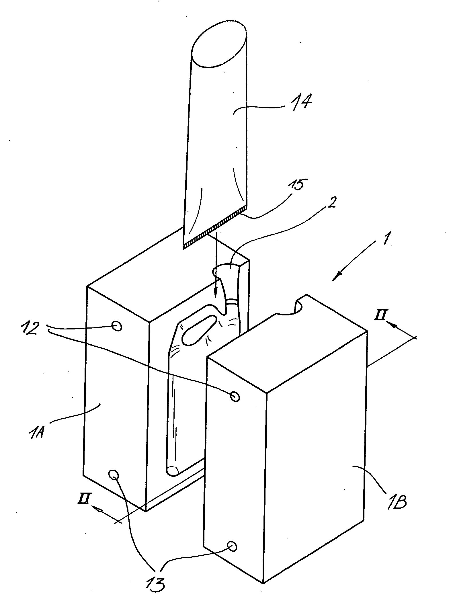
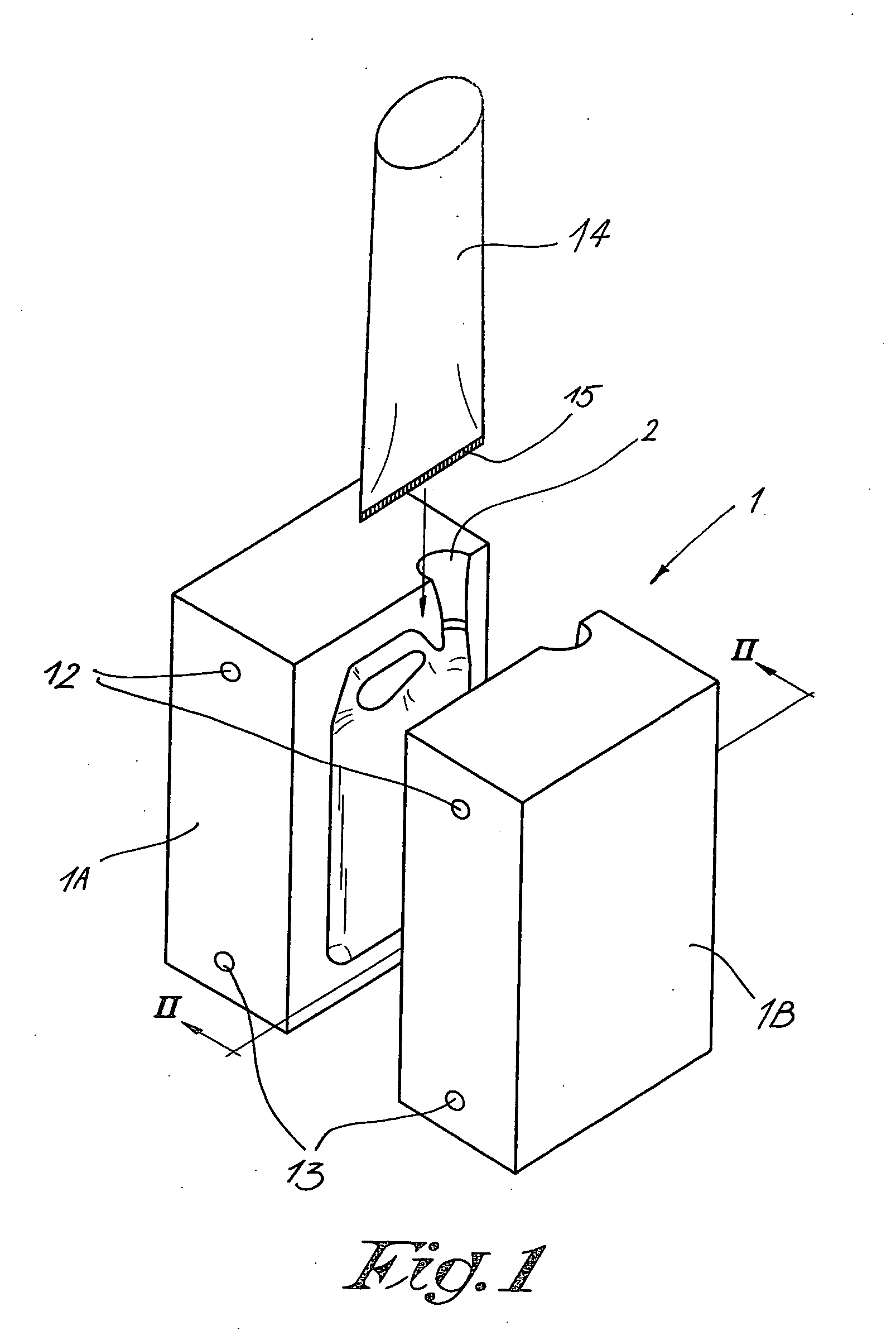
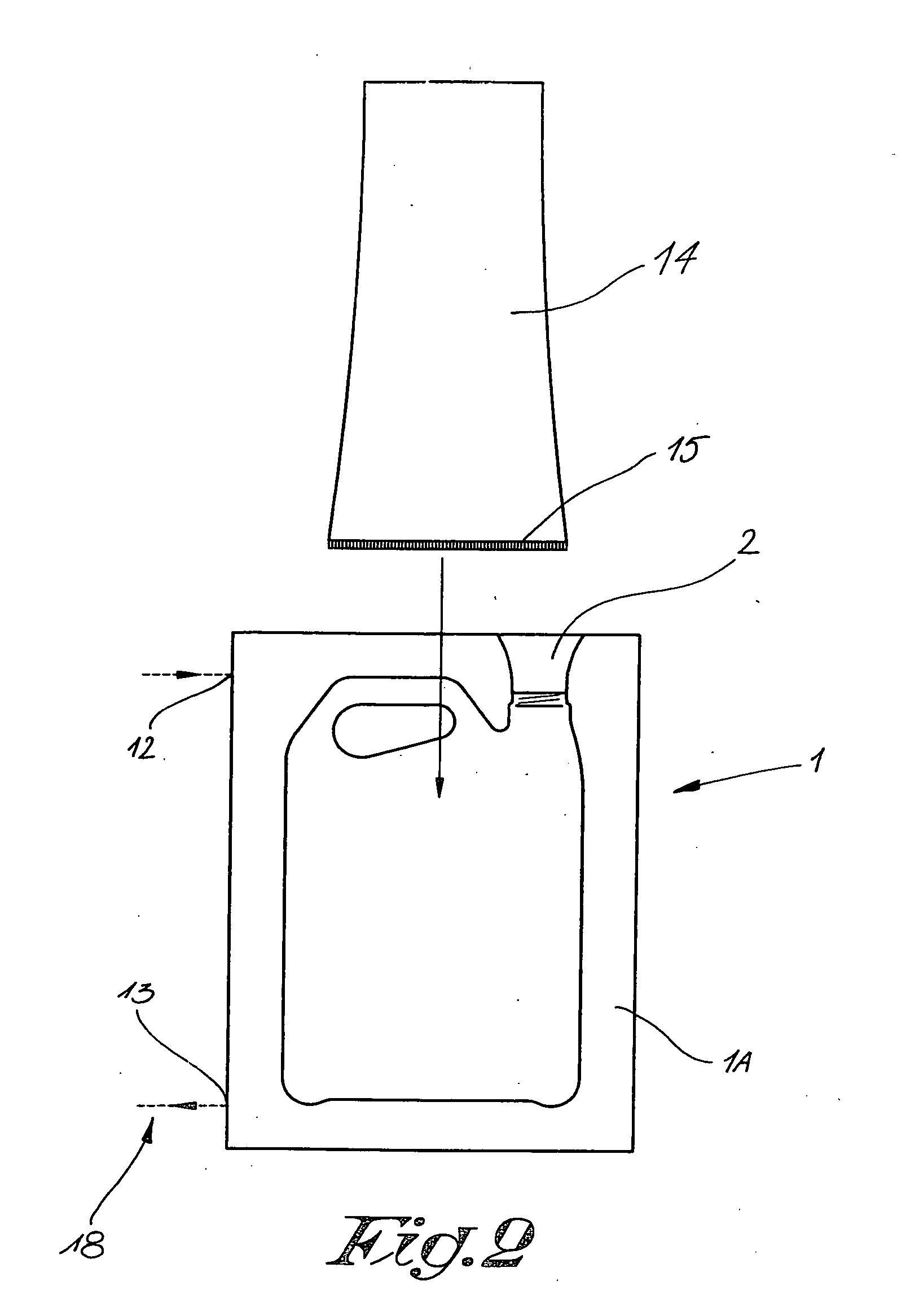
[0027] FIGS. 1 to 5 represent a mould 1 for blowing synthetic objects, for example in this case canisters for storing liquids, which mould 1 is made in two parts in the known manner, whereby these two mould parts 1A and 1B, can be moved away from each other and towards each other by means of a driving mechanism which is not represented in the figures.

[0028] In the above-mentioned mould 1 is provided at least one opening 2 in which can be provided a blowing needle or blowing mandrel 3 to blow an object 4.

[0029] The above-mentioned blowing mandrel 3 in this case consists of two concentric ducts for compressed air, more specifically an inner supply duct 5 and an outer discharge duct 6.

[0030] The supply duct 5 is hereby connected to a compressed air network 7 which may for example be provided with an adjustable inlet cock 8.

[0031] The outlet of the discharge duct 6 is, in this case, connected to the atmosphere via an adjustable throttle valve 9, which throttle valve 9 is preferably ...


PUM

PropertyMeasurementUnit
temperatureaaaaaaaaaa
relative pressureaaaaaaaaaa
pressureaaaaaaaaaa

Abstract

A method for blowing objects, in which the following steps are successively followed: providing a synthetic sleeve (14) in a mould (1); inflating this sleeve (14) by means of compressed air up to a maximum pressure; and scavenging the obtained object (4) by means of a compressed air flow, whereby the air in the object (4) is continuously refreshed, wherein the pressure of the compressed air varies from a start pressure to the atmospheric pressure according to an adjustable course which varies as a function of time.

Description

BACKGROUND OF THE INVENTION [0001] 1. Field of the Invention [0002] The present invention concerns a method for blowing objects, such as bottles, canisters or the like. [0003] 2. Discussion of the Related Art [0004] It is known that hollow, plastic objects can be formed by what is called “twin sheet molding”, which consists of welding two vacuum-formed pieces together and cooling them. For this technique, use is made of a blowing needle or blowing mandrel in the known manner. [0005] It is also known that such objects can be blown out of plastic, whereby a synthetic sleeve is inserted in a mould having the shape of the object to be made and this sleeve is then inflated by means of compressed air, and the formed object is taken out of the mould after cooling off. [0006] For blowing, this known technique makes use of a blowing mandrel or blowing needle. [0007] Inflating is usually done with pre-blowing, whereby the inflating takes place at a small air pressure which is then increased t...

Claims


Application Information

Patent Timeline
Patent Type & Authority Applications(United States)
IPC IPC(8): B29C39/02B29C35/16B29C49/04B29C49/48B29C49/58B29C49/60B29C49/66B29C49/78
CPCB29C49/04B29C49/4823B29C49/58B29C49/60B29C49/4284B29C49/783B29C2035/1616B29C2049/6615B29C2049/6646B29C49/66Y02P70/10B29C49/42855B29C49/4286B29C2049/7833B29C2049/7835
Inventor DE BRUYN, DANNYLEMEIRE, RUDY
Owner DELTA ENG MET
Why Eureka
Try Eureka