
Plasma display panel and flat lamp using oxidized porous silicon

a technology of oxidized porous silicon and display panel, which is applied in the manufacture of electrodes, electrode systems, electric discharge tubes/lamps, etc., can solve the problems of low secondary electron emission coefficient and easy deterioration of fluorescent layers, and limit the electron-emitting effect of plasma, so as to increase the electron-emitting

Inactive Publication Date:
View PDF8 Cites 16 Cited by
  • Summary
  • Abstract
  • Description
  • Claims
  • Application Information

AI Technical Summary

Benefits of technology

[0016] The present invention provides a plasma display panel (PDP) and a flat lamp using oxidized porous silicon to increase an electron-emitting property.

Problems solved by technology

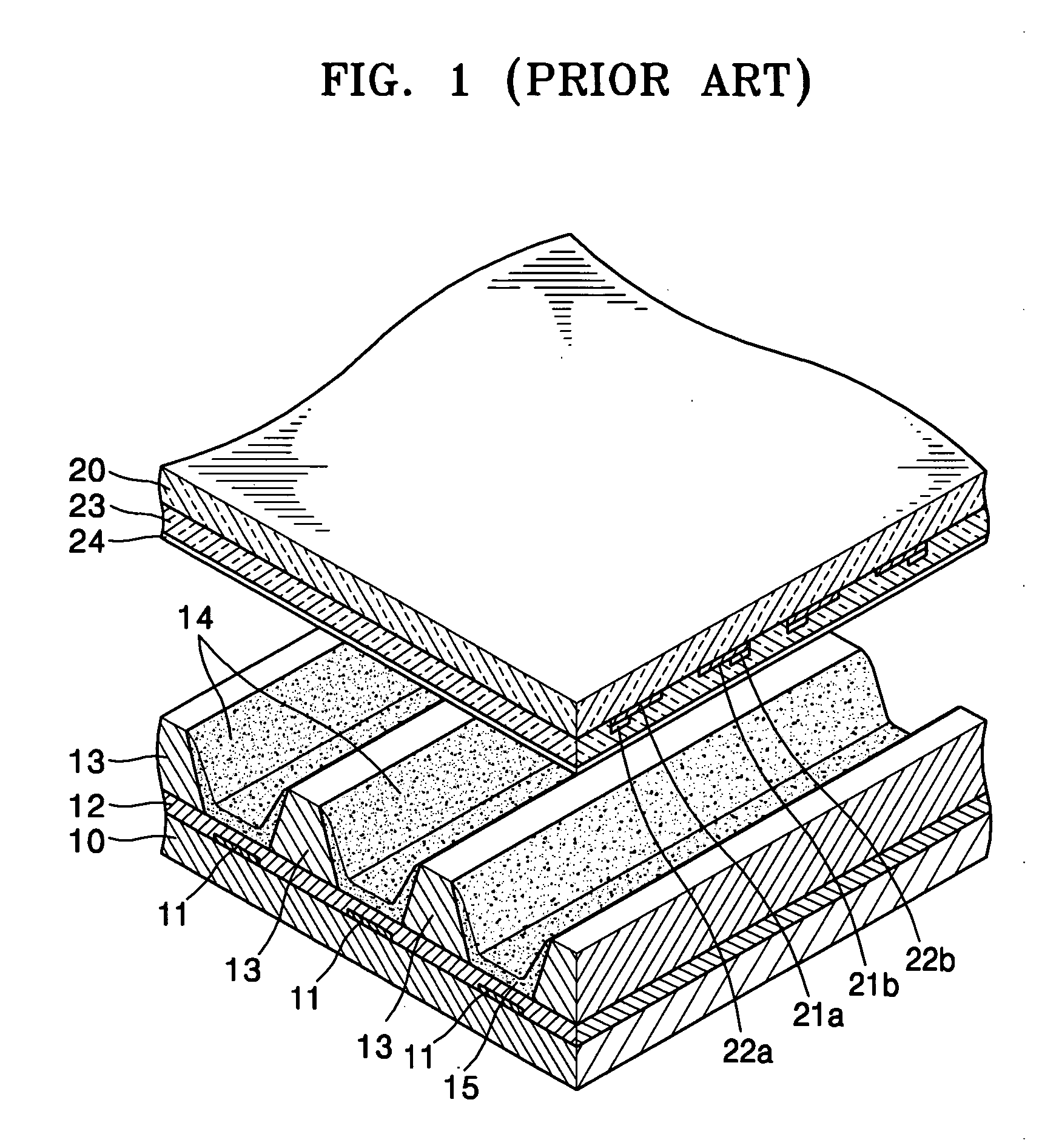
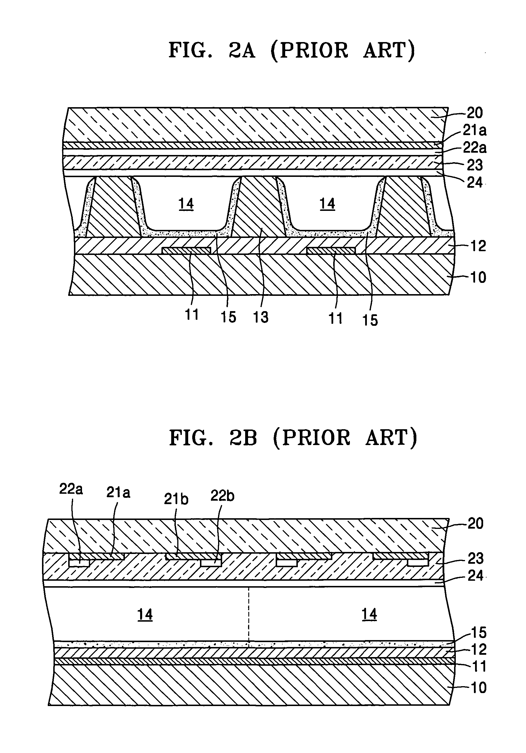
While the facing discharge type PDP may have high luminous efficiency, plasma may easily deteriorate a fluorescent layer.
However, an MgO protective layer's low secondary electron emission coefficient limits its electron-emitting effects.

Method used


Image

  • Plasma display panel and flat lamp using oxidized porous silicon
  • Plasma display panel and flat lamp using oxidized porous silicon
  • Plasma display panel and flat lamp using oxidized porous silicon

Examples


Embodiment Construction

[0046] Hereinafter, exemplary embodiments of the present invention will be described with reference to the attached drawings. Throughout the drawings, the same reference numerals denote the same constitutional elements.

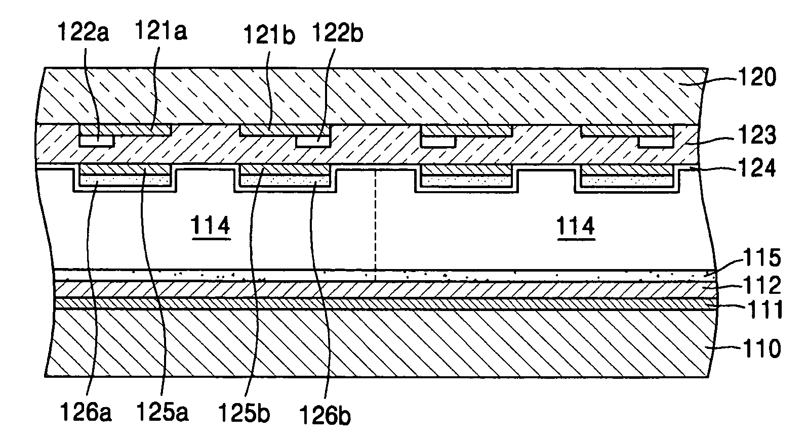
[0047]FIG. 4 is an exploded perspective view showing a plasma display panel (PDP) according to an embodiment of the present invention, and FIG. 5 is a cross-sectional view of a portion of the PDP of FIG. 4.

[0048] Referring to FIG. 4 and FIG. 5, the PDP according to an embodiment of the present invention may include an upper panel and a lower panel facing each other. A plasma is discharge occurs in a discharge space between the upper panel and the lower panel. A plurality of barrier ribs 113 divide the discharge space into discharge cells 114 and prevent electrical and optical cross-talk between adjacent discharge cells 114. A discharge gas, which generates ultraviolet rays during a discharge, is injected into the discharge cells 114. Generally, a mixed gas of Ne and...


PUM


Abstract

A plasma display panel (PDP) and a flat lamp. The PDP includes an upper panel and a lower panel facing each other, a plurality of address electrodes formed in the lower panel, a plurality of sustaining electrodes formed in the upper panel, and an oxidized porous silicon layer formed in the upper panel and corresponding to a sustaining electrode.

Description

CROSS REFERENCE TO RELATED APPLICATIONS [0001] This application claims priority to and the benefit of Korean Patent Application No. 10-2004-0054488, filed on Jul. 13, 2004, and Korean Patent Application No. 10-2004-0103670, filed on Dec. 9, 2004, which are hereby incorporated by reference for all purposes as if fully set forth herein. BACKGROUND OF THE INVENTION [0002] 1. Field of the Invention [0003] The present invention relates to a plasma display panel (PDP) and a flat lamp, and more particularly, to a PDP and a flat lamp using oxidized porous silicon to increase an electron-emitting characteristic. [0004] 2. Discussion of the Background [0005] Generally, PDPs, which form an image using a gas discharge, may have excellent display characteristics such as high luminance and a wide viewing angle. Hence, their popularity is increasing. In PDPs, applying a direct current (DC) or alternating current (AC) voltage to electrodes may cause a gas discharge between the electrodes, thereby g...

Claims


Application Information

Patent Timeline
Patent Type & Authority Applications(United States)
IPC IPC(8): H01J17/49H01J9/02H01J11/12H01J11/22H01J11/24H01J11/26H01J11/30H01J11/34H01J11/38H01J11/40H01J11/44H01J61/06H01J61/30H01J65/00
CPCH01J9/02H01J9/14H01J11/12H01J11/28H01J2211/225H01J61/12H01J61/16H01J61/305H01J65/046H01J11/40
Inventor SON, SEUNG-HYUNHATANAKA, HIDEKAZUKIM, YOUNG-MOLEE, HO-NYEONJANG, SANG-HUNLEE, SEONG-EUIPARK, HYOUNG-BINKIM, GI-YOUNG
Learn More