

Vacuum tube power amplifier switchable between push-pull and single ended configurations
a technology of vacuum tubes and power amplifiers, which is applied in amplifiers, amplifiers with semiconductor devices/discharge tubes, amplifiers, etc., can solve the problems of low frequency roll-off, reduced magnetic flux capability, and failure to switch between push-pull and single-ended construction, etc., to achieve touch sensitive dynamic nuance, increase loudness and distortion, and notable “fat”.
- Summary
- Abstract
- Description
- Claims
- Application Information
AI Technical Summary
Benefits of technology
Problems solved by technology
Method used
Image

Examples
Embodiment Construction
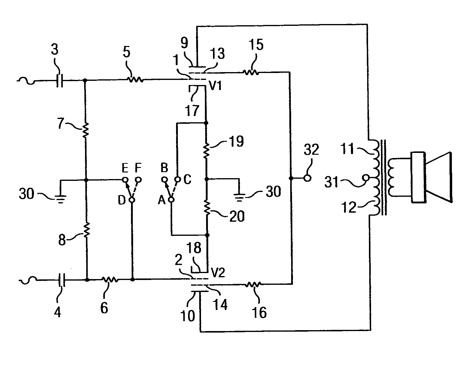
[0014] Referring to FIG. 1, opposing phase push-pull AC signals are provided for the signal grids 1, 2 of vacuum tube power pentodes V1 and V2 respectively. The AC signals are coupled through blocking capacitors 3, 4 and grid stop resistors 5, 6. Grid leak resistors 7, 8 provide DC reference to ground 30 for the grids 1, 2. Anodes 9, 10 of pentodes V1 and V2 are fed DC high voltage through respective halves of the output of transformer primary winding 11, 12. DC voltage from the power supply (not shown) enters the output transformer primary winding 11, 12 through center tap 31. Screen grids 13, 14 are coupled to the high voltage DC source at 32 via current limiting resistors 15 and 16. Cathodes 17, 18 are coupled to ground 30 through respective cathode bias resistors 19, 20. Switches A, B, C and D, E, F operate in conjunction with each other and may be a double pole double throw (DPDT) relay device. When configured as shown by the arrows, connection D to E effectively grounds the gr...
PUM
 Abstract
Description
Claims
Application Information