Head-mounted pointing and control device

a control device and head-mounted technology, applied in computing, instruments, electric digital data processing, etc., can solve the problems of difficult to remove the requirement, inconvenient and limited computer operation, difficult to control computer concepts, etc., to avoid the collection of clogging debris and convenient placement

a control device and head-mounted technology, applied in computing, instruments, electric digital data processing, etc., can solve the problems of difficult to remove the requirement, inconvenient and limited computer operation, difficult to control computer concepts, etc., to avoid the collection of clogging debris and convenient placement

US20060012571A1Active Publication Date: 2006-01-19ALKEN INC DBA POLHEMUS

Image

  • Head-mounted pointing and control device
  • Head-mounted pointing and control device
  • Head-mounted pointing and control device

Examples


Embodiment Construction

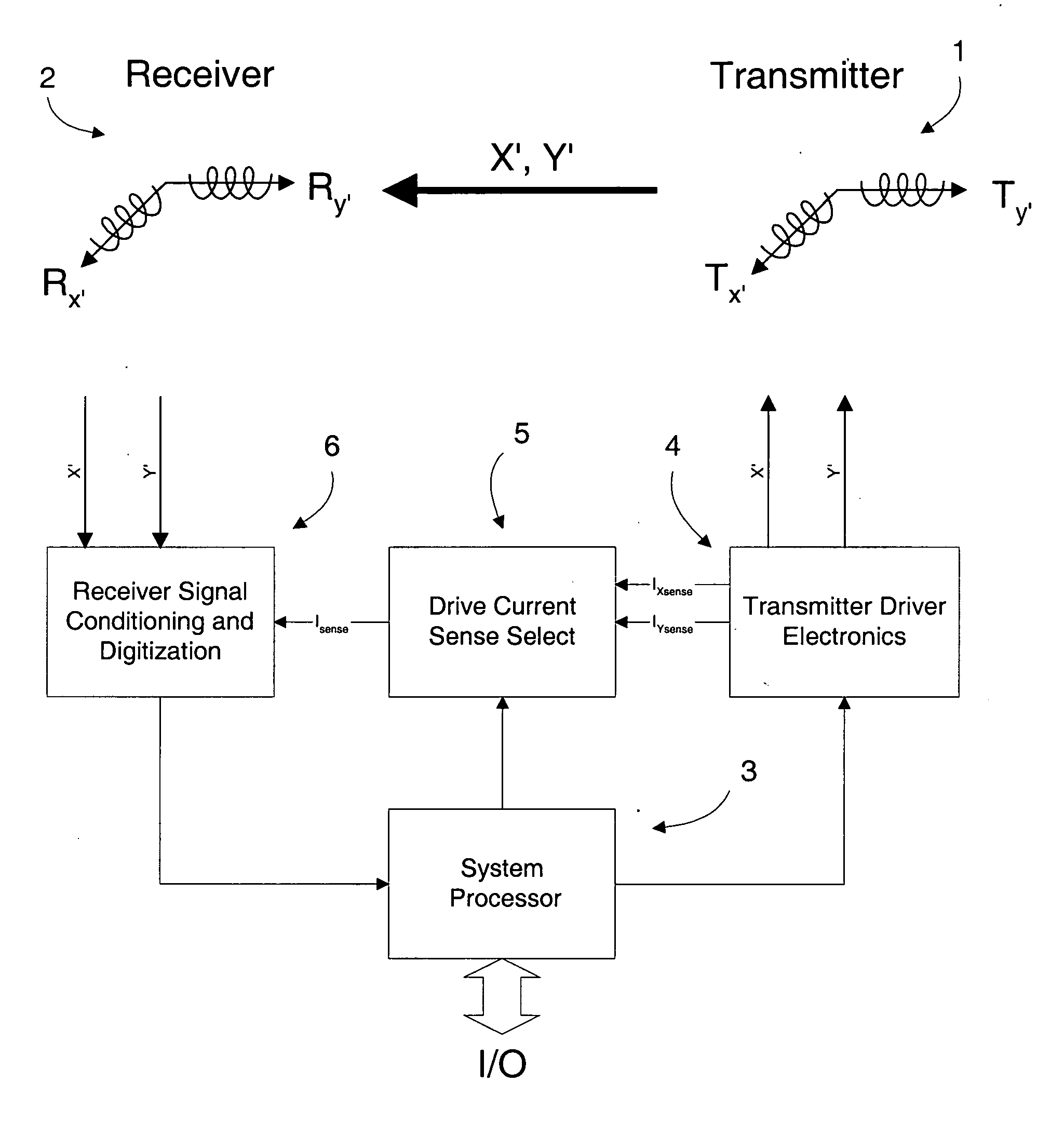
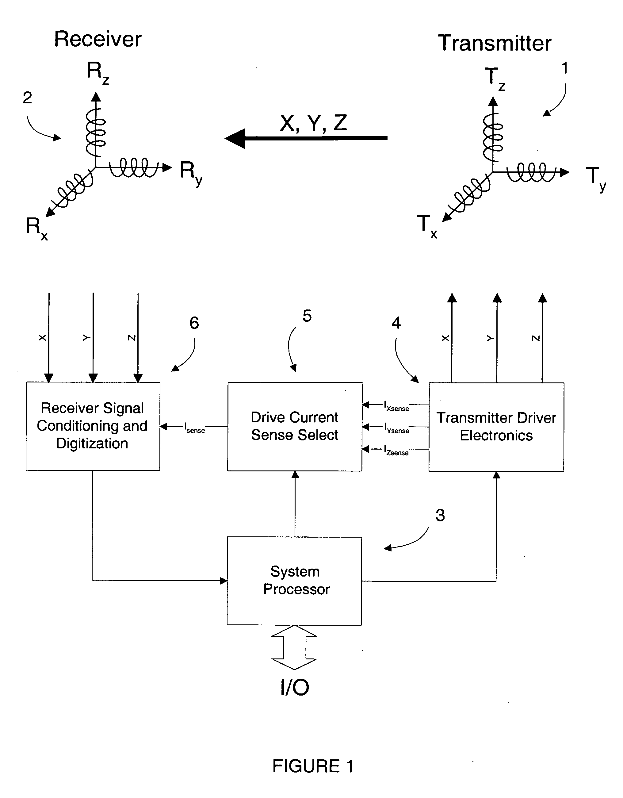
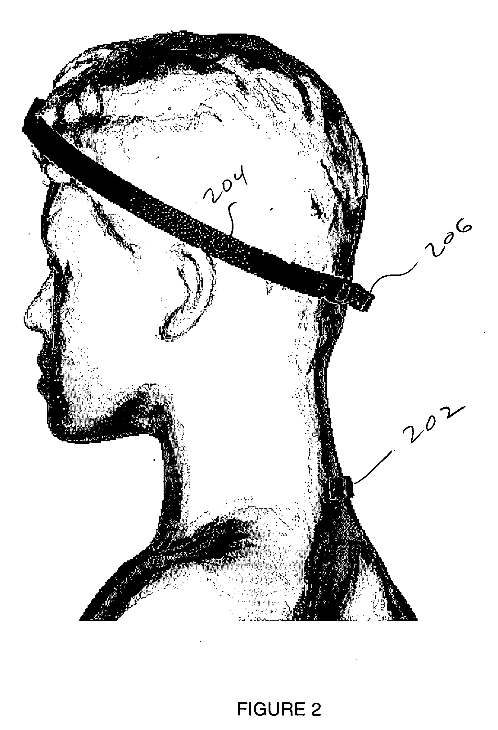
[0018] This invention broadly applies technologies used for tracking head movement in virtual reality games and military helmet mounted displays to provide a wireless, hands-free cursor control or “mouse.” As such, mouse and cursor movements are made by monitoring user head movements and actuation / selection by a key on the keyboard where the hands are already employed, thereby eliminating the disruption of locating and manipulating a conventional mouse device. Alternatively, the tracking of particular head nods, twists and / or shakes may be processed via software to emulate mouse button actuations, leading to a control device for use by a person whose hands are otherwise involved in holding or employing a tool or instrument. Such a capability is particularly important to users lacking in hand mobility or dexterity, or indeed even missing a hand.

[0019] As opposed to a complex head / helmet tracking device, which is extremely costly and provides much more capability than is actually req...


PUM


Abstract

A magnetic tracker system for use on an operator's head makes “mouse” / cursor movements on a screen similar to that of the classic computer “mouse” / track ball / touchpad / joystick. Only head movements are used as opposed to lifting a hand from the keyboard for making such moves. The new “mouse” avoids interrupting the hands from their position on the keyboard and has no moving mechanical parts that become clogged and that need a special surface (mouse pad) or special surface measurements (optical mouse).

Description

REFERENCE TO RELATED APPLICATION [0001] This application claims priority from U.S. Provisional Patent Application Ser. No. 60 / 587,709, filed Jul. 14, 2004, the entire content of which is incorporated herein by reference.FIELD OF THE INVENTION [0002] This invention is related to computer pointing devices and, in particular, to hands-free alternatives to the conventional “mouse.”BACKGROUND OF THE INVENTION [0003] The so-called computer “mouse,” and other pointing devices such as the trackball, touchpad and joystick, have allowed the computer industry to use the display monitor as a continuously variable control and data input device. This has made difficult computer concepts available and controllable by individuals not at all versed in the computer art. [0004] There are situations, however, where the mouse is inconvenient and limiting to computer operation because of the necessity for the user to remove his / her hands from the keyboard, or to empty at least one hand from carrying an i...

Claims


Application Information

Patent Timeline
19 Jan 2006
Publication
US20060012571A1
IPC
G09G5/08
CPC
G06F3/012
Inventors
RODGERS, ALLAN G.; HIGGINS, ROBERT F.