Liquid crystal display device

a liquid crystal display and display device technology, applied in static indicating devices, instruments, optics, etc., can solve the problems of narrow viewing angle, low response speed, and panel unsuitability for displaying moving images

Inactive Publication Date: 2006-01-19
JAPAN DISPLAY CENT INC
View PDF4 Cites 14 Cited by
  • Summary
  • Abstract
  • Description
  • Claims
  • Application Information

AI Technical Summary

Benefits of technology

[0030] The present invention has been made in order to solve the foregoing problem. It is an object of the present invention to provide a liquid crystal display device

Problems solved by technology

Although this TN-type liquid crystal display panel can be comparatively easily manufactured, its viewing angle is narrow, and its response speed is low.
Thus, this panel has been unsuitable to display a moving image such as a television image, in particular.
Thus, it is presumed that the external environment of the system used largely changes, and consequently, the ambient temperature of the liquid crystal display panel significantly changes from below 0° C. to about 80° C. The use under an environment condition which is severer than the use in room such as a television set is unavoidable.
In particular, in a low temp

Method used


Image

  • Liquid crystal display device
  • Liquid crystal display device
  • Liquid crystal display device

Examples


Embodiment Construction

[0048] A liquid crystal display device according to one embodiment of the present invention will be described in detail with reference to the accompanying drawings.

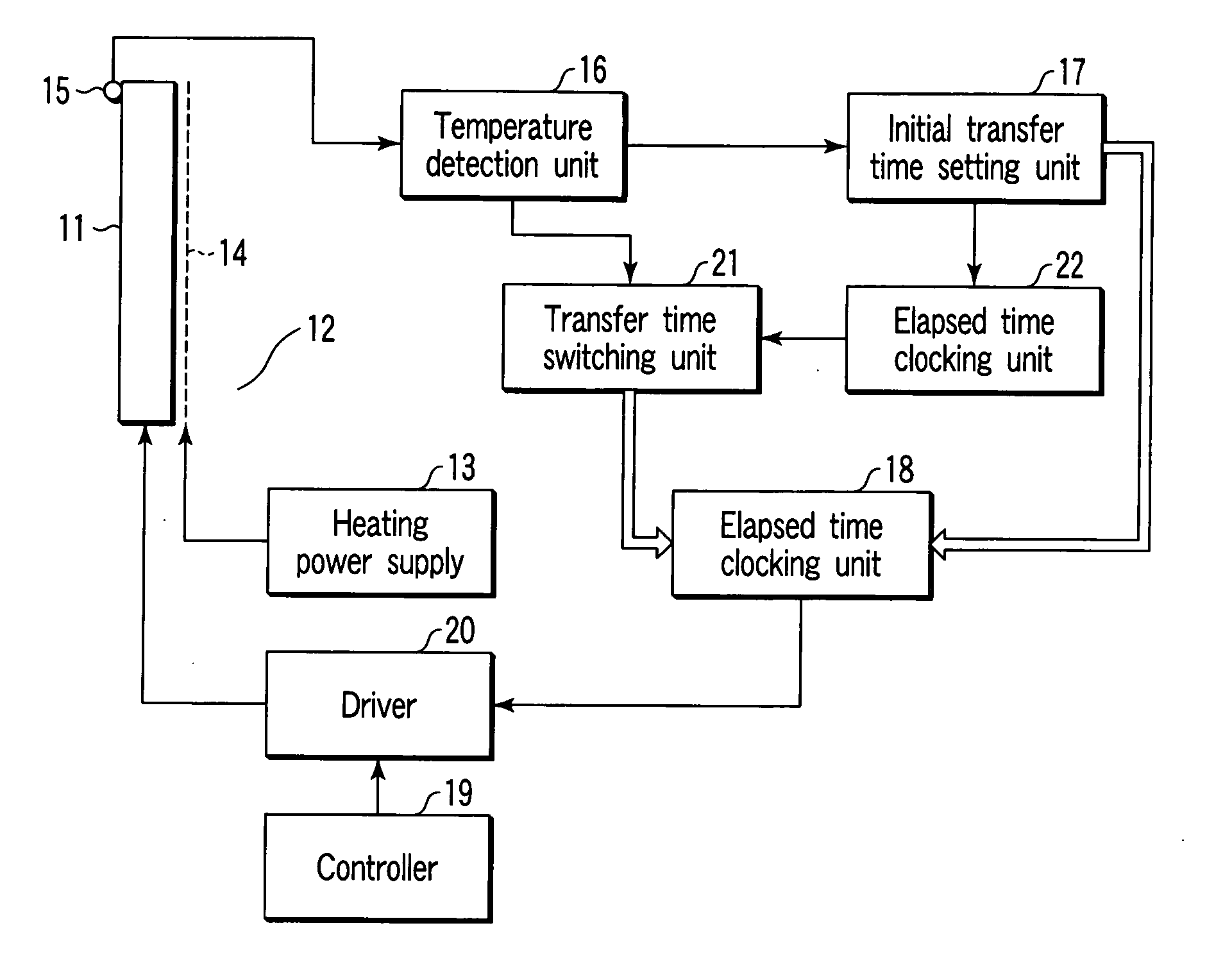
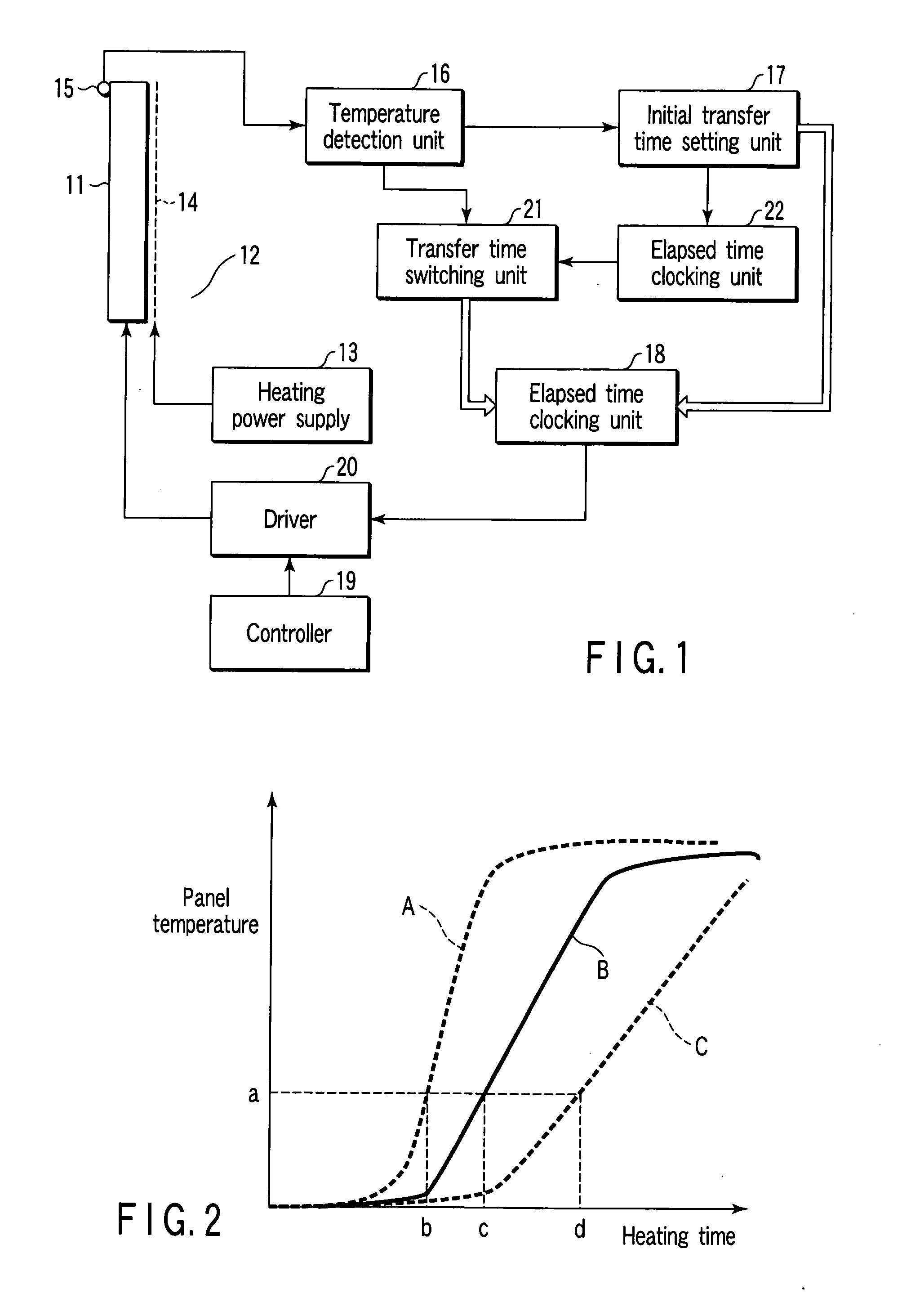
[0049] In the liquid crystal display device, as shown in FIG. 1, a heater 14 is provided near the liquid crystal display panel 11 on the back side opposite to a display screen as a heating unit 12, and is connected to a heating power supply 13 for selectively supplying power that allows the heater 14 to heat as required. A thermal sensor 15 is installed for sensing a temperature of the liquid crystal display panel 11.

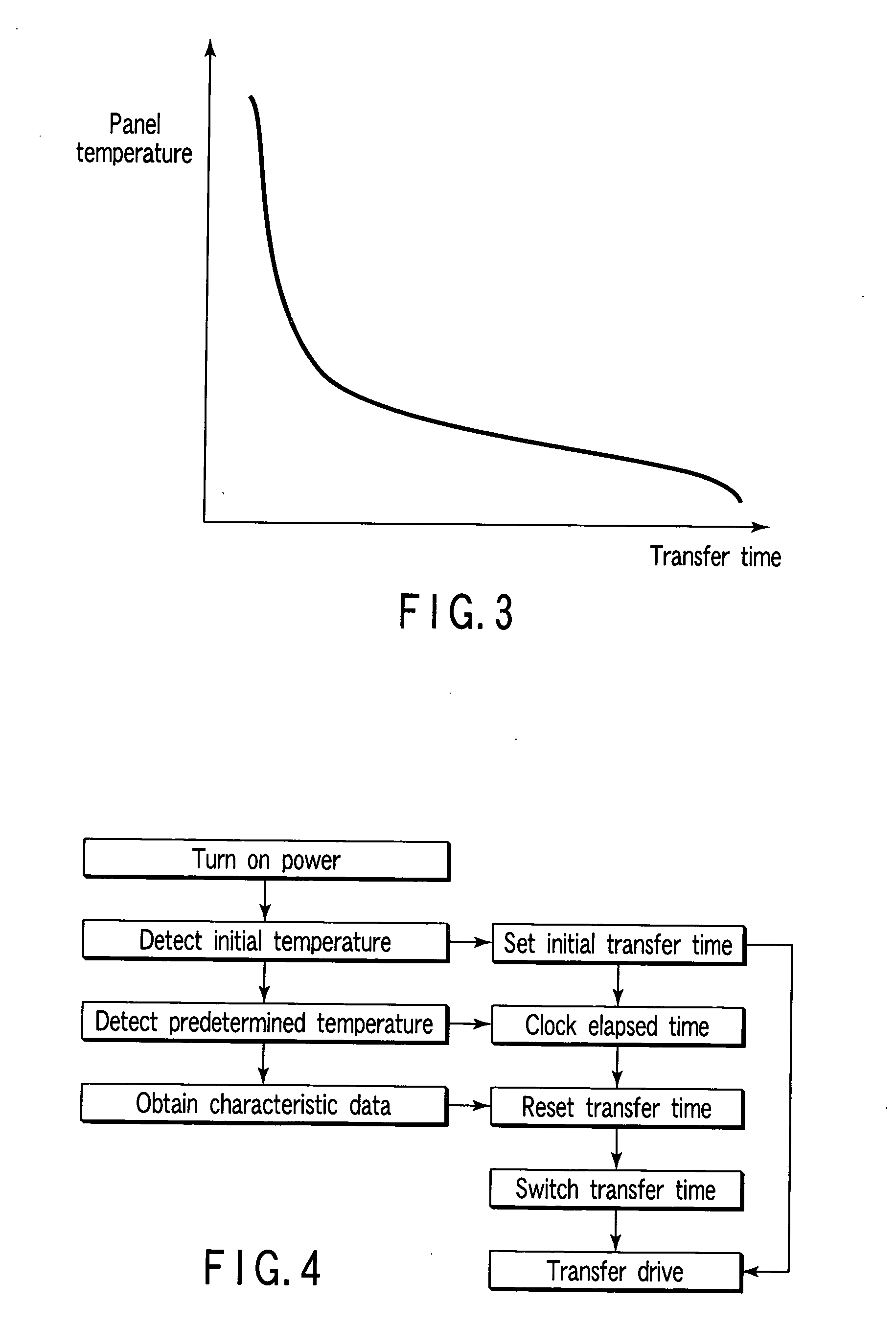
[0050] On the other hand, the thermal sensor 15 is connected to a temperature detecting unit 16 so as to detect or measure the temperature of the liquid crystal display panel 11. Information on the detected temperature is supplied to an initial transfer time setting unit 17. The initial transfer time setting unit 17 sets an initial transfer time based on the detected temperature and drives a transfer drive ...


PUM


Abstract

A liquid crystal display device comprises a liquid crystal display panel including a liquid crystal layer for a display in an OCB mode, a heating unit which heats the liquid crystal display panel, a temperature detecting unit for detecting a temperature of the liquid crystal display panel, a time measuring unit which measures a heating time that the heating unit has operated, and a transfer drive circuit which applies a transfer drive voltage to the liquid crystal layer to transfer the alignment state of liquid crystal molecules from a splay alignment to a bend alignment in advance. The transfer drive circuit is configured to determine a transfer time as an application period of the transfer drive voltage on the basis of a relationship between the heating time and temperature which are obtained from the time measuring unit and temperature detecting unit at a desired timing.

Description

CROSS-REFERENCE TO RELATED APPLICATIONS [0001] This application is based upon and claims the benefit of priority from prior Japanese Patent Application No. 2004-168590, filed Jun. 7, 2004, the entire contents of which are incorporated herein by reference. BACKGROUND OF THE INVENTION [0002] 1. Field of the Invention [0003] The present invention relates to a liquid crystal display device, and more particularly, to a liquid crystal display device capable of providing a wide viewing angle and high-speed response. [0004] 2. Description of the Related Art [0005] Currently, a liquid crystal display panel utilizing characteristics such as lightness, thinness, and low power consumption is used as a display for use in television sets, personal computers and car navigation systems. [0006] A twisted nematic (TN) type liquid crystal display panel widely utilized as this liquid crystal display panel is configured such that a liquid crystal material having optically positive refractive anisotropy ...

Claims


Application Information

Patent Timeline
IPC IPC(8): G09G5/00G02F1/139G02F1/133G02F1/1337G09G3/20G09G3/36
CPCG02F1/133382G09G3/3648G09G2330/026G09G2320/0252G09G2320/041G09G3/3655
Inventor TAKEOKA, MASAHIKO
Owner JAPAN DISPLAY CENT INC
Why Eureka
Try Eureka