Ink jet recording apparatus, recording head and ink jet recording method

a recording apparatus and ink jet technology, applied in the direction of printing, inking apparatus, etc., can solve the problems of increasing the load in the drive reducing the carriage speed in the main scanning direction, and increasing the load in the driving circuit of the recording head

Active Publication Date: 2006-01-19
KONICA MINOLTA MEDICAL & GRAPHICS INC
View PDF2 Cites 34 Cited by
  • Summary
  • Abstract
  • Description
  • Claims
  • Application Information

AI Technical Summary

Benefits of technology

[0092] Accordingly, by using the recording head of the 3-phase drive, the same effects as in each of the above aspect of the present invention can be achieved.

Problems solved by technology

However, as the recording head has higher density of nozzles, the number of nozzles simultaneously driven becomes larger, which increases the current flowing at the leading edge of drive, to thereby increase the load in drive circuits for the recording head.
However, when pixels are recorded in a straight line using staggered nozzles on a recording head with multi-phase drive as in the conventional printer, each phase has to be switched within one pixel time, so that the carriage speed in the main scanning direction has been limited by nozzle-drive frequency of the recording head.
On the other hand, the larger number of drive phases need the larger number of switching of strobe pulses, which causes strobe pulse width to be relatively narrower, resulting in relatively lower carriage speed.
The carriage speed in the main scanning direction has been also limited by the staggered pitch between nozzles on a recording head.
However, the larger staggered pitch makes the size of recording head larger, and also causes a problem in that it needs a new manufacturing technology for producing recording heads having a larger staggered pitch.
As described above, an ink jet recording apparatus, having staggered nozzles on the head with multi-phase drive, is limited in achieving higher carriage speed, because the carriage speed limitation depends on the nozzle-drive frequency and the staggered pitch.
Therefore, even if there exist misalignment of nozzles, or ink jet failure in some nozzles, these irregularities could be made averaged, and perceived as unnoticeable misalignment of recorded pixels.
To the contrary, line-type ink jet recording apparatuses, which employ recording heads for multi-phase drive, also have the same problems as in the serial-type ink jet recording apparatuses.
However, the larger staggered pitch makes the size of recording head larger.
As described above, if pixels were recorded in a line using the multi-phase drive recording head having staggered nozzles thereon, the recording speed has been inevitably limited in both line type and serial type ink jet recording apparatuses, because the feeding speed or carriage speed, i.e., recording speed depends on the nozzle-drive frequency and the staggered pitch.

Method used


Image

  • Ink jet recording apparatus, recording head and ink jet recording method
  • Ink jet recording apparatus, recording head and ink jet recording method
  • Ink jet recording apparatus, recording head and ink jet recording method

Examples


first embodiment

a. First Embodiment

[0174] A first embodiment of the invention will now be explained with reference to FIGS. 1 to 7.

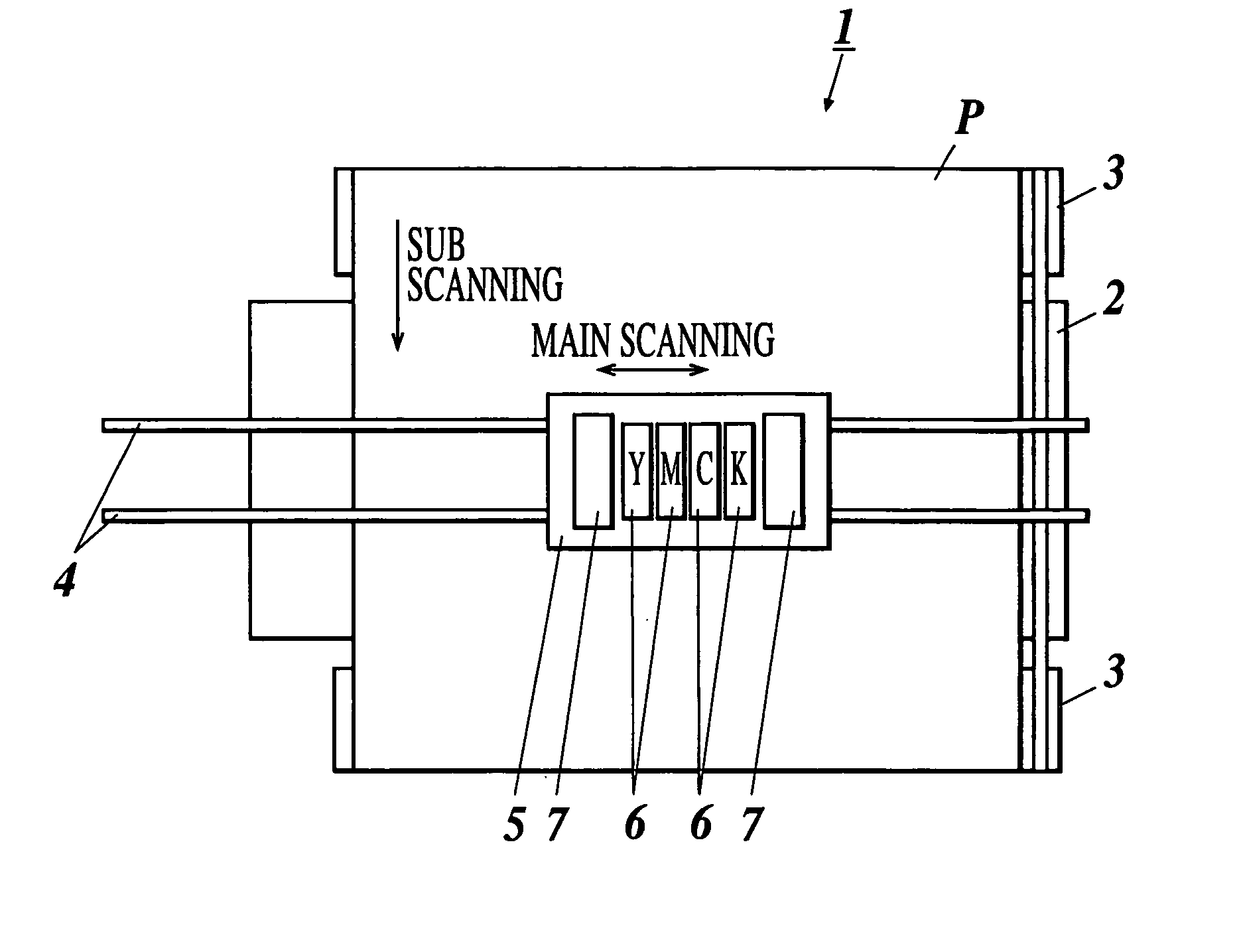
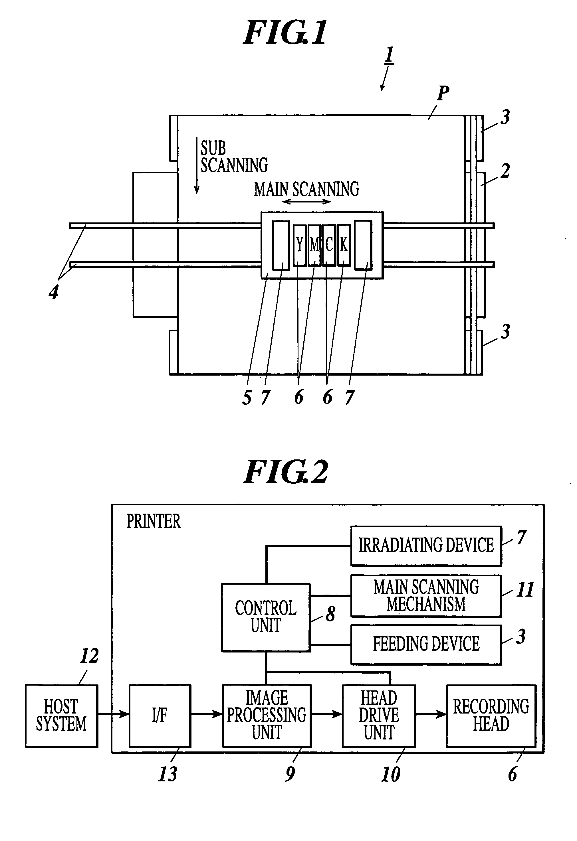
[0175]FIG. 1 shows the schematic construction of an ink jet recording apparatus 1 according to the embodiment.

[0176] The ink jet recording apparatus 1 is a serial type ink jet recording apparatus in which recording heads 6 scan in a direction (main scanning direction) perpendicular to a feeding direction of a recording medium P with the jetting of ink droplets during head movement to form images. This ink jet recording apparatus 1 has a platen 2 supporting the medium P from its underside as shown in FIG. 1. There are provided with feeding devices 3, each device including a roller for feeding the medium P, at the upstream and downstream sides in the medium feeding direction (sub scanning direction) of the platen 2 so as to dispose the platen 2 between them. Provided over the platen 2 is a pair of guide rails 4 extending in the main scanning direction. The guide rails 4...

second embodiment

b. Second Embodiment

[0230] A second embodiment of the invention will now be explained with reference to FIGS. 8 to 12.

[0231] An ink jet recording apparatus 1 in the embodiment is a serial type ink jet recording apparatus, and similar to the first embodiment comprises a platen 2, feeding devices 3, guide rails 4, and a carriage 5 having recording heads 6 and irradiating devices 7 mounted thereon.

[0232] However, each recording head 6 of the embodiment has staggered nozzles arranged thereon. A staggered pitch is the value of a recorded pixel pitch divided by the number of drive phases. In the embodiment, the recorded pixel pitch is one inch (25400 μm) / 720 dpi, and the number of drive phases is three, therefore the staggered pitch is 11.759 μm.

[0233] As shown in FIG. 2, the ink jet recording apparatus 1 comprises a control unit 8. The control unit 8 is electrically connected to an image processing unit 9, a head drive unit 10 for driving recording heads, a main scanning mechanism 11,...

third embodiment

c. Third Embodiment

[0262] A third embodiment of the invention will now be explained with reference to FIGS. 13 to 20.

[0263] An ink jet recording apparatus 1 in the embodiment is a serial type ink jet recording apparatus, and similar to the first embodiment in that the printer 1 comprises a platen 2, feeding devices 3, guide rails 4, and a carriage 5 having recording heads 6 and irradiating devices 7 mounted thereon.

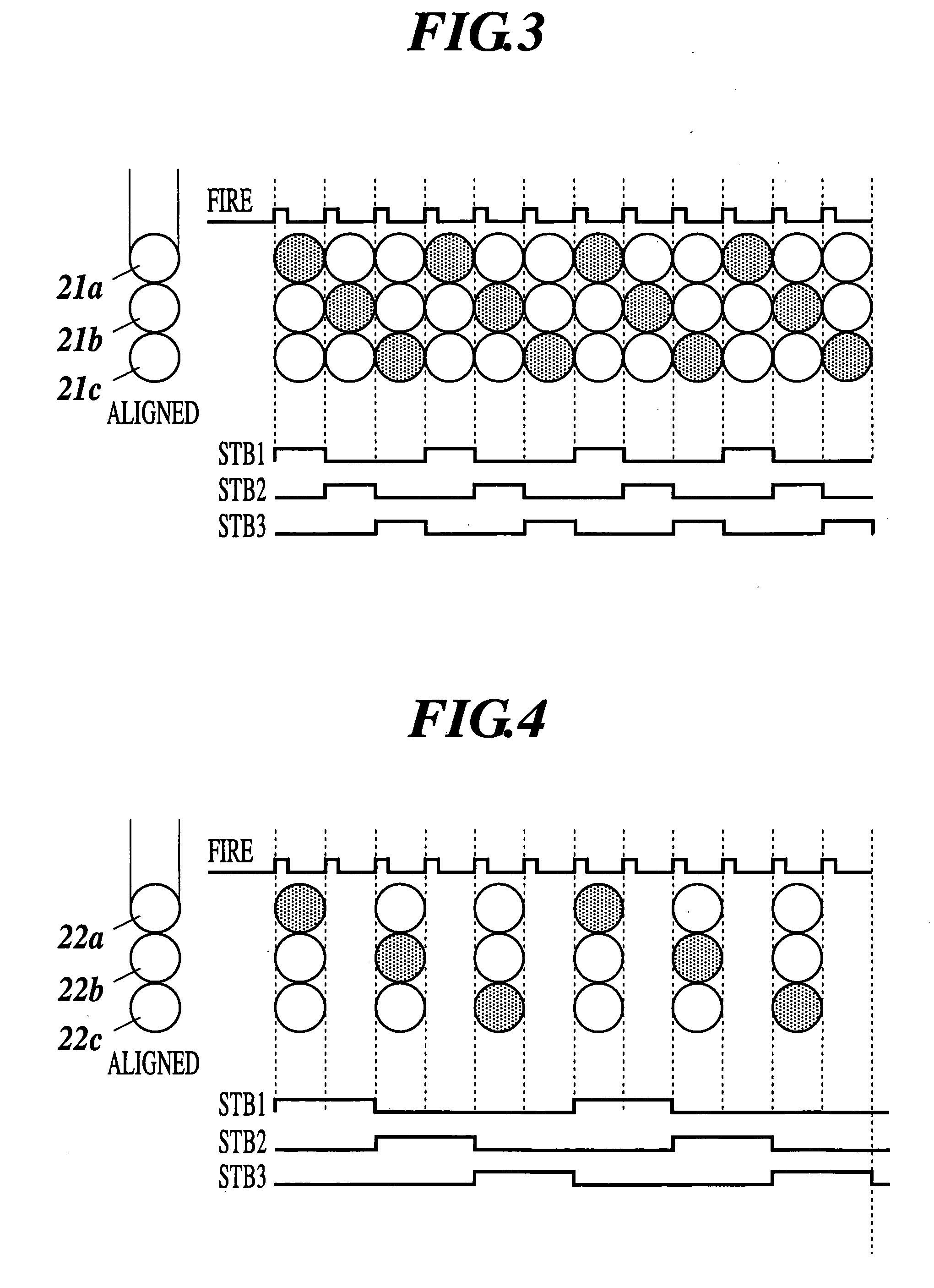
[0264] However, in the embodiment, each recording head 6 comprises nozzle columns of multiples of the number of drive phases, which comprises nozzles jetting the same kind of ink. The nozzles are arranged in a straight line for each column. A description will be given below of a case in which three columns of the aligned nozzles are used with 3-phase drive.

[0265] In order to provide three nozzle columns, each nozzle jetting the same kind of ink, as shown in FIG. 13, for example, one recording head 6 has three nozzle columns 14a, 14b and 14c formed thereon for jetting t...


PUM


Abstract

An ink jet recording apparatus having: a recording head having a plurality of nozzles formed thereon to jet ink; a feeding device to feed a recording medium; and a control unit to control ink jetting from the nozzles of the recording head so that the recording head is driven with multi-phase drive to record with recorded pixel locations shifted at every drive phase switching by an integer times a pixel width of a recording resolution.

Description

BACKGROUND OF THE INVENTION [0001] 1. Field of the Invention [0002] The present invention relates to an ink jet recording apparatus, a recording head and an ink jet recording method, and more particularly to an ink jet recording apparatus that employs a recording head for multi-phase drive and an ink jet recording method using this apparatus. [0003] 2. Description of the Related Art [0004] There has been known an ink jet recording apparatus as a recording apparatus capable of printing on various kinds of recording mediums, such as standard paper and the like. The ink jet recording apparatus jets ink, serving as a coloring agent, directly on a recording medium from nozzles mounted on the surface of a recording head opposing to the recording medium, the ink landing, being absorbed or fixed on the medium, to thus form an image on the recording medium. The ink jet recording apparatus has several superior advantages, such as simple processing, quietness at the time of printing, and high ...

Claims


Application Information

Patent Timeline
Patent Type & Authority Applications(United States)
IPC IPC(8): B41J2/145B41J2/15
CPCB41J2202/20B41J2/145
Inventor NIEKAWA, YUKIHIRO
Owner KONICA MINOLTA MEDICAL & GRAPHICS INC
Why Eureka
Try Eureka