
HTML driven embedded controller

Active Publication Date: 2006-01-19
YORK INT
View PDF29 Cites 66 Cited by
  • Summary
  • Abstract
  • Description
  • Claims
  • Application Information

AI Technical Summary

Benefits of technology

[0010] An advantage of the present invention is that a local user such as an on-site technician, as well as remote users such as off-site contractors or other authorized remote users, can access the web site of the controller and be linked with the controlled equipment for gathering and monitoring of data, as well as for control of the displayed parameters such as the language of text, units of measure, and types of data displayed without disrupting the data that may be displayed on devices of other users who are simultaneously accessing the controller.
[0011] Another advantage of the present invention is that the use of a website generated by a dedicated HTML-driven controller permits data transfer from particular items of building equipment to remotely located users, without the need for networking the controller or item of controlled equipment to a BAS or other local computer network.
[0012] Another advantage of the present invention is that the use of a website generated by a dedicated HTML-driven controller provides a quick and easy way for equipment information to be accessed by both local and remote users.
[0013] Yet another advantage of the present invention is that it permits a remotely located contractor to monitor numerous pieces of equipment, including equipment located at different geographical sites, without the need for a dedicated connection to any non-Internet computer network(s) that might otherwise control the building equipment.
[0014] Still another advantage of the present invention is that it allows service personnel to troubleshoot equipment problems from remote locations, such as their home or office, by providing access to an Internet website generated by the controller, thus allowing them to see exactly what an on-site operator of the equipment would see on a local display linked to the equipment, allowing less service calls while maintaining adequate equipment and customer service.

Problems solved by technology

Due to their logic structure, PLCs, as opposed to microprocessors, can only handle a very limited number of logic functions, and can only perform a very limited number of calculations or other tasks simultaneously.
These requirements, combined with the limited logic capability and slow processing speed of known PLCs, make PLCs a poor choice for flexible and intelligent control of building equipment.
Furthermore, in typical known embedded controllers, only about twenty percent (20%) of the software program is dedicated to control of the equipment.

Method used


Image

  • HTML driven embedded controller
  • HTML driven embedded controller
  • HTML driven embedded controller

Examples


Embodiment Construction

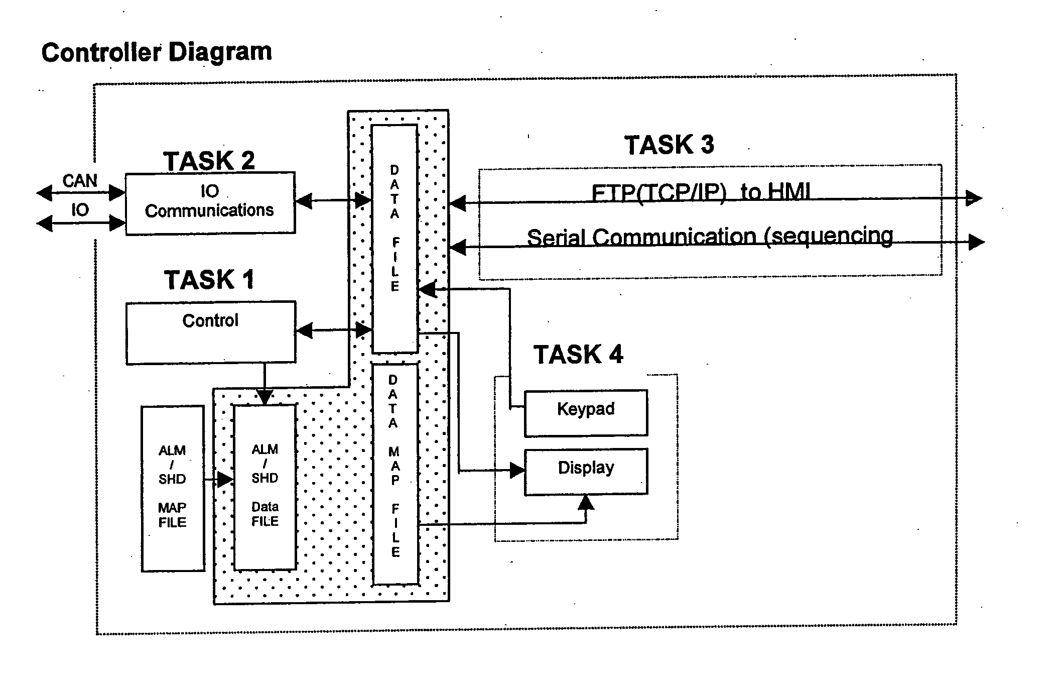
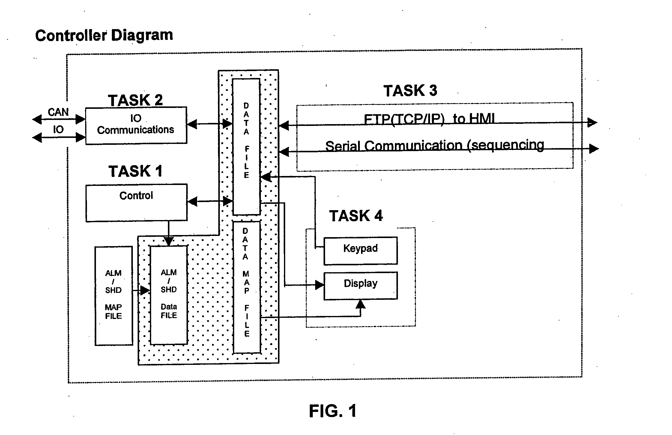
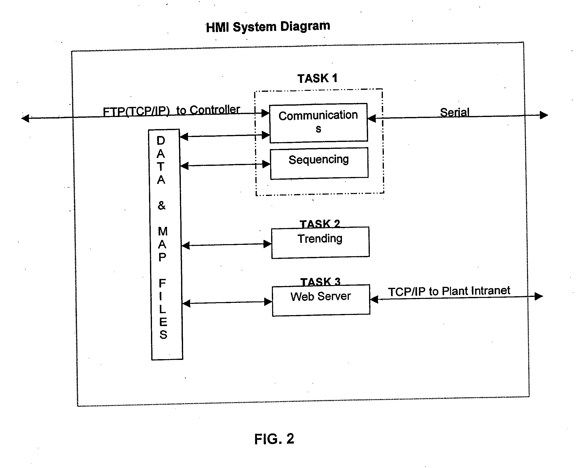
[0021] A system is provided to facilitate monitoring and control of particular items of building equipment, including stand-alone and networked items of equipment (such as in a BAS), by locally and remotely located users, such as on-site technicians and off-site service contractors. The system includes an HTML driven embedded controller for HVAC&R equipment and other building systems, and methods that permit remote access and remote control of the controller and associated equipment through an Internet-based website.

[0022] In one embodiment, the controller of the present invention includes a microprocessor (also known as a Central Processing Unit or “CPU”) that can generate an interface for a user to control an item of equipment. The interface is presented as a web page that is generated by a web server incorporated in the controller. The web page can be directly viewed on a connected local display screen. Additionally, because the interface is provided as a web page having a uniqu...


PUM


Abstract

A method and system is provided for gathering, processing, displaying, and manipulating data from building equipment using a dedicated HTML-driven, non-PLC controller having an integral web server. Authorized users who use microprocessor controlled devices to access the website are provided with displayed equipment data that can be selected, monitored, and adjusted based on a user profile controlled by software of the controller.

Description

CROSS-REFERENCE TO RELATED APPLICATIONS [0001] This application claims the benefit of U.S. Provisional Application No. 60 / 587,920 filed Jul. 14, 2004.FIELD OF THE INVENTION [0002] The present invention is directed to a system and method for communicating or for the transport of electronic data and information from controlled building equipment to local and remotely located users. More particularly, this invention is directed to a system and method for providing data and information from particular items of controlled building equipment, such as heating ventilation air-conditioning and refrigeration (hereinafter “HVAC&R”) equipment, to a user, such as a servicing technician or contractor, using a dedicated Hypertext Markup Language (“HTML”) embedded, non-PLC, controller that collects and serves data to a website generated by a web server in the controller. The website can be accessed and reviewed by remotely located users on remotely located devices, and can simultaneously be accesse...

Claims


Application Information

Patent Timeline
IPC IPC(8): G05B15/00G01M1/38G05B13/00G05B21/00G05D23/00
CPCG05B19/0428G05B19/058G05B19/4186G05B2219/34444G05B2219/2638G05B2219/31085G05B2219/31457G05B2219/2614Y02P90/02
Inventor LEHMAN, DELMAR EUGENETHRUSH, DENNIS R.
Owner YORK INT
Learn More