System and shadow bistable circuits coupled to output joining circuit

a shadow bistable, output joining circuit technology, applied in the field of electronic devices, can solve problems such as system-level soft error rate, digital system also may be susceptible to single event transients (sets), and may be significant soft errors

Inactive Publication Date: 2006-01-19
INTEL CORP
View PDF4 Cites 26 Cited by
  • Summary
  • Abstract
  • Description
  • Claims
  • Application Information

AI Technical Summary

Problems solved by technology

Soft errors may be significant for microprocessors, network processors, high end routers and network storage components that target enterprise and applications where high reliability, data integrity and availability are desirable.
Sequential circuits, such as bistable circuits (e.g., latches and flip-flops), may be major contributors to the system-level soft error rate.
In addition to soft errors in bistable circuits, the digital systems also may be susceptible to single event transients (SETs), which are soft errors originating in combinational logic circuits that drive the latches and flip-flops.

Method used


Image

  • System and shadow bistable circuits coupled to output joining circuit
  • System and shadow bistable circuits coupled to output joining circuit
  • System and shadow bistable circuits coupled to output joining circuit

Examples


Embodiment Construction

[0019] In the following description, for purposes of explanation, numerous details are set forth in order to provide a thorough understanding of the disclosed embodiments of the present invention. However, it will be apparent to one skilled in the art that these specific details are not required in order to practice the disclosed embodiments of the present invention. In other instances, well-known electrical structures and circuits are shown in block diagram form in order not to obscure the disclosed embodiments of the present invention.

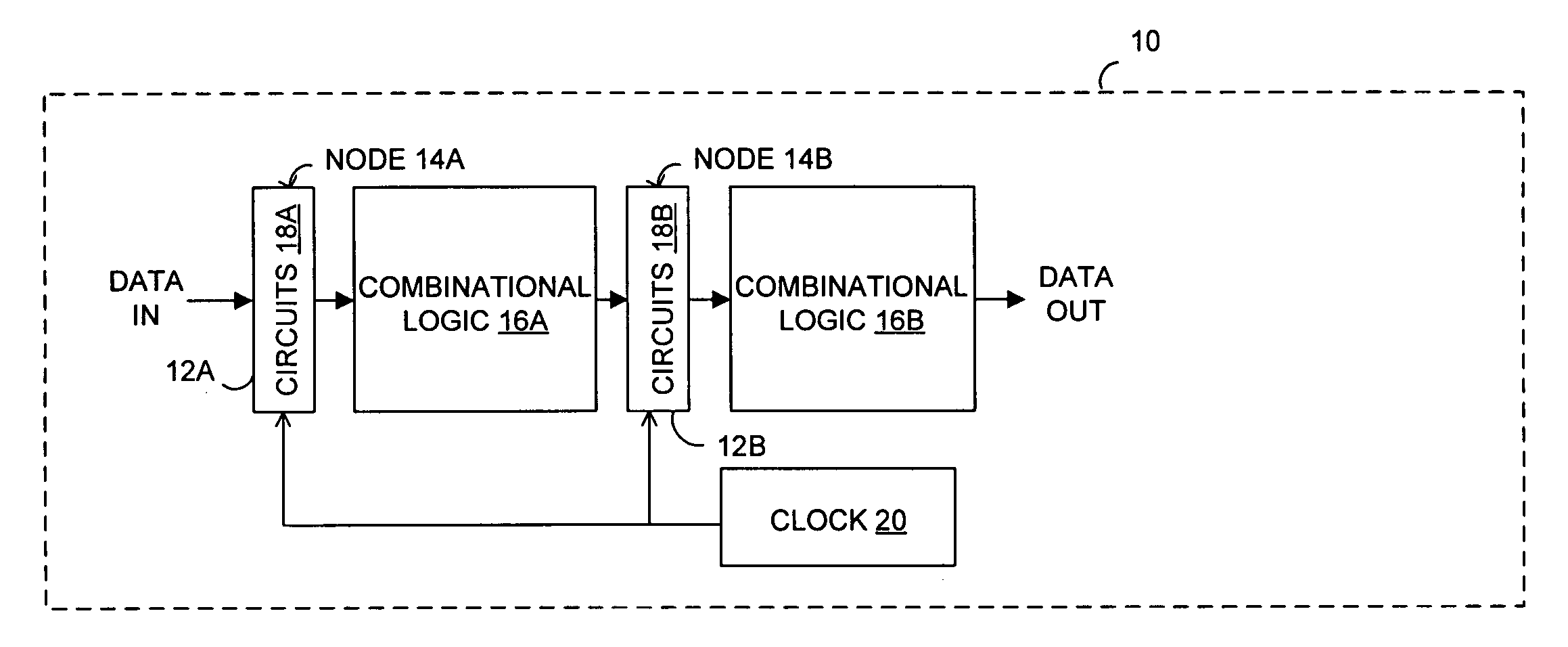
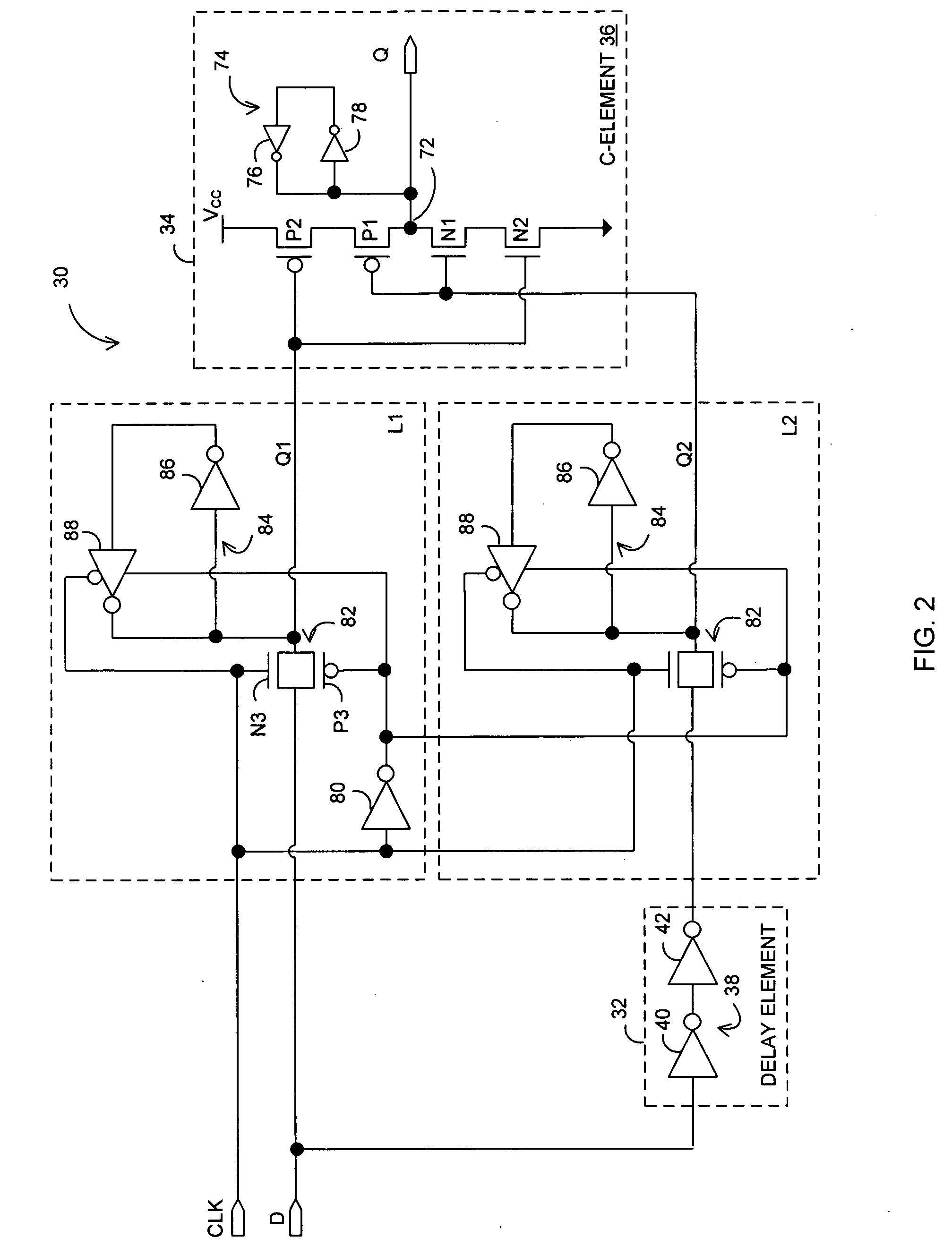
[0020] Various embodiments according to the present invention are directed toward enabling bistable circuits (e.g., latches and flip-flops) with built-in resilience (hardening, self-checking or correcting) to single event upsets (SEUs) occurring in the bistable circuits, while also providing protection against single event transients (SETs) occurring in combinational logic circuits interposed between the bistable circuits. More specifically, in a fi...


PUM


Abstract

In one embodiment, an apparatus is provide with a combinational logic circuit to generate a data input signal; a delay element, coupled to the combinational logic circuit, to provide a delayed data input signal in response to the data input signal. Additionally, the apparatus is provided with a system bistable circuit, coupled to the combinational logic circuit, to generate a system bistable signal in response to at least the data input signal; a shadow bistable circuit, coupled to the delay element, to generate a shadow bistable signal in response to at least the delayed data input signal. Further, the apparatus is provided with an output joining circuit, coupled to the system and the shadow bistable circuits, to provide a data output signal in response to the system and the shadow bistable signals.

Description

CROSS-REFERENCE TO RELATED APPLICATIONS [0001] This application is a continuation-in-part of: (a) copending U.S. patent application Ser. No. 10 / 882,523 (“523”), filed Jun. 30, 2004, entitled “Error Detecting Circuit”; (b) copending U.S. patent application Ser. No. 11 / 044,826 (“826”), filed Jan. 26, 2005, entitled “System And Shadow Circuits With Output Joining Circuit”; (c) copending U.S. patent application Ser. No. 11 / 050,996 (“996”), filed Feb. 4, 2005, entitled “System and Scanout Circuits with Error Resilience Circuit”; and (d) copending U.S. patent application Ser. No. 11 / 128,692 (“692”), filed May 12, 2005, entitled “System Pulse Latch and Shadow Pulse Latch Coupled to Output Joining Circuit”, and this application claims priority to the '523, '826, '996 and '692 applications.BACKGROUND [0002] 1. Technical Field [0003] Embodiments of the present invention are related to the field of electronic devices, and in particular, to errors in electronic devices. [0004] 2. Description of...

Claims


Application Information

Patent Timeline
Patent Type & Authority Applications(United States)
IPC IPC(8): G01R31/28
CPCG01R31/318536G01R31/318525
Inventor MITRA, SUBHASISHZHANG, MINGKIM, KEE SUP
Owner INTEL CORP
Why Eureka
Try Eureka