HCCI engine combustion control

a technology of combustion control and combustion chamber, which is applied in the direction of electrical control, process and machine control, instruments, etc., can solve the problems of increasing the oxygen level of the cylinder, increasing the temperature of the cylinder, etc., and achieve the effect of reducing differences

Active Publication Date: 2006-01-26
GM GLOBAL TECH OPERATIONS LLC
View PDF9 Cites 49 Cited by
  • Summary
  • Abstract
  • Description
  • Claims
  • Application Information

AI Technical Summary

Benefits of technology

[0007] In accordance with one aspect of the present invention, an internal combustion engine is operated unthrottled with homogeneous charge compression ignition. The engine is operated with predetermined external EGR and internal EGR settings. Desired burned gas fraction set points for intake and exhaust gases are provided. Repetitive determinations of burned gas fraction values of the intake and exhaust gases are made and differences from the corresponding desired burned gas fraction set points are calculated. Repetitive adjustments are made to the external EGR and internal EGR settings to move the burned gas fraction values of the intake and exhaust gases toward their corresponding set points. Adjustments made to the internal EGR setting are made with respect to a negative valve overlap setting when the engine is operated in an exhaust recompression mode. Adjustments made to the internal EGR setting are made with respect to an exhaust valve lift reopening setting when the engine is operated in an exhaust rebreathing mode. The method may also include the provision of a desired cylinder combustion phasing set point. Repetitive determinations of current combustion phasing values are made and differences from the desired cylinder combustion phasing set point are calculated. And, repetitive adjustments are made to the desired burned gas fraction set point for intake gases to reduce differences between current combustion phasing values and the desired cylinder combustion phasing set point. Combustion phasing set points may be with respect to location of peak pressure in the cylinders or location of combustion of one half the fuel supplied for each cylinder cycle.

Problems solved by technology

For example, if the exhaust valve closes earlier during the exhaust stroke, more hot exhaust gas from the previous engine cycle would be trapped in the cylinder, leaving less cylinder volume for the fresh air mass, thereby, increasing the cylinder temperature, while decreasing the cylinder oxygen level.

Method used


Image

  • HCCI engine combustion control
  • HCCI engine combustion control

Examples


Embodiment Construction

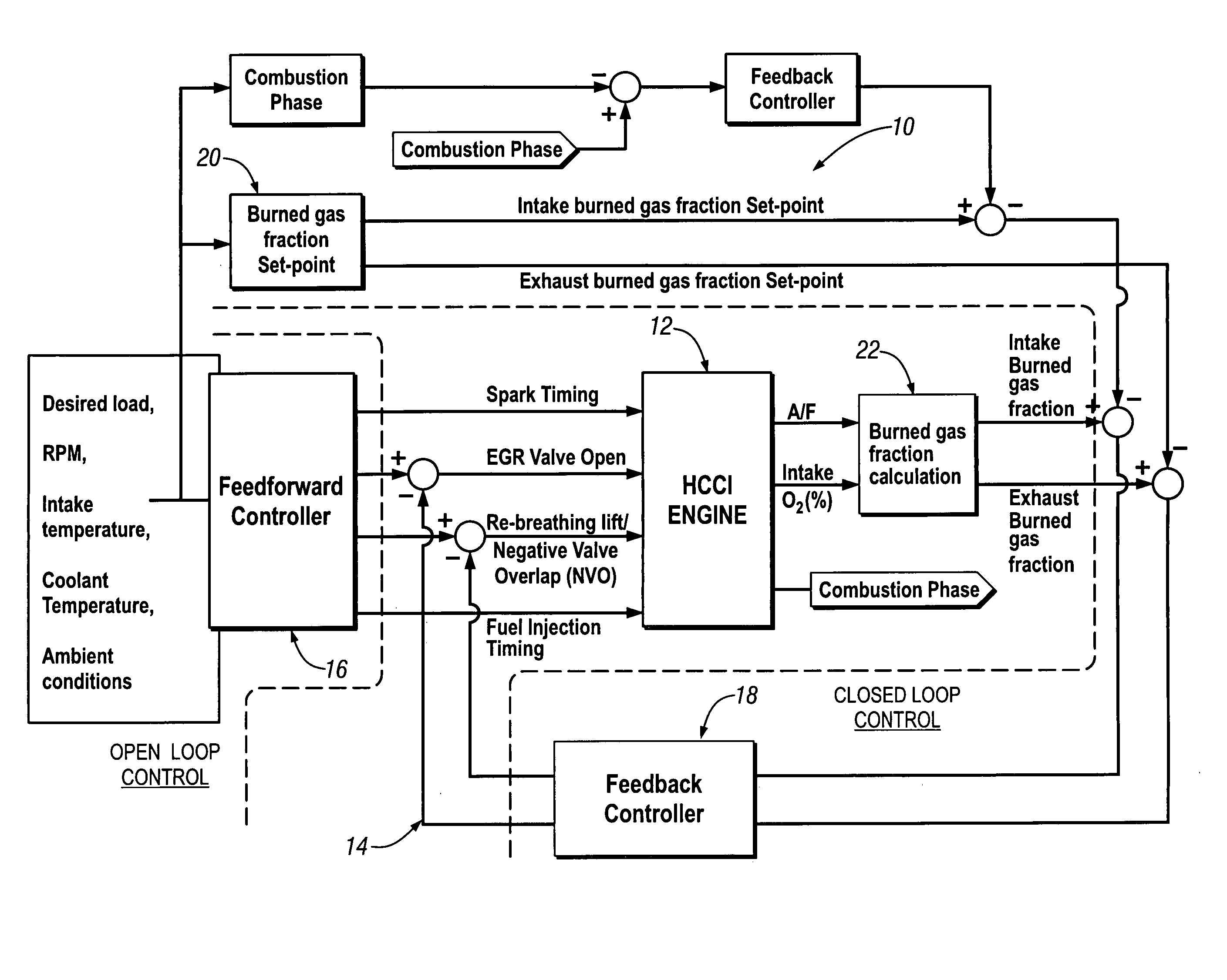
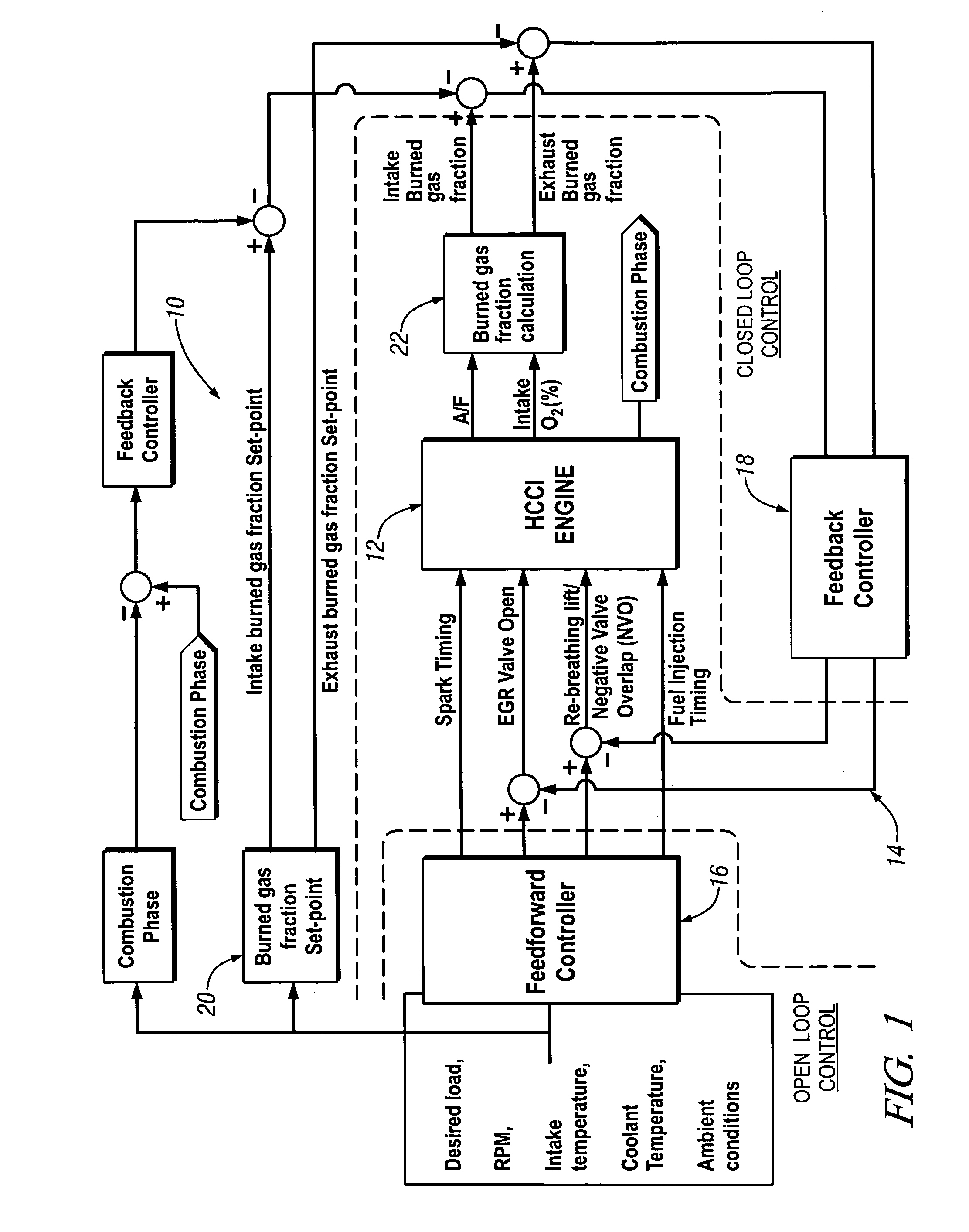
[0013] Referring now to the single figure of the drawing in detail, numeral 10 generally indicates a block diagram showing an engine 12 capable of operating with homogeneous charge compression ignition (HCCI) and a combustion control system 14 and method for controlling combustion in the engine.

[0014] The engine 12 may include various features or devices, not shown, including power producing combustion chambers (which may be in cylinders with reciprocating pistons) connected with an intake air system and an exhaust system, intake and exhaust valves with some form of variable valve timing operative to control fluid intake to and exhaust flow from the combustion chambers, an external exhaust recirculation system including an EGR valve connected between the intake and exhaust systems, and fuel injection and spark ignition systems for supplying fuel to and igniting or assisting ignition of combustible mixtures in the combustion chambers.

[0015] The engine 12 is designed to operate on f...


PUM


Abstract

An exemplary method of controlling a gasoline engine operating unthrottled with homogeneous charge compression ignition (HCCI) combustion includes operating the engine with predetermined values of external EGR and internal EGR settings, and burned gas fraction set points for intake and exhaust gases. Repeated adjustments are made to the external EGR and internal EGR settings to move the exhaust and intake gases burned gas fractions toward their state set points. Effects of disturbances in actual operating conditions are thereby minimized.

Description

CROSS-REFERENCE TO RELATED APPLICATIONS [0001] This application claims priority from U.S. Provisional Patent Application No. 60 / 589,652 filed Jul. 21, 2004.TECHNICAL FIELD [0002] This invention relates to homogeneous charge compression ignition (HCCI) spark ignition engines and, more particularly, to control of combustion in such engines BACKGROUND OF THE INVENTION [0003] In an HCCI engine, the phasing of auto-ignited combustion strongly depends on the cylinder charge temperature, composition, and the cylinder pressure at intake valve closing. Hence, the input to the engine, such as amount of fuel, fuel injection timing, spark timing, EGR valve opening, and intake and exhaust valve profiles, must be carefully coordinated to ensure that those key cylinder variables are within a range where the auto-ignited combustion can be robustly achieved. Among those inputs, the most effective input that has a significant impact on cylinder variables is the intake and exhaust valve profiles, and ...

Claims


Application Information

Patent Timeline
Patent Type & Authority Applications(United States)
IPC IPC(8): F02M25/07F02B75/02
CPCF02B1/12Y02T10/18F02D13/0242F02D13/0265F02D13/0273F02D35/028F02D41/0052F02D41/0062F02D41/0072F02D41/3035F02D2013/005F02D2041/141F02D2041/1419F02M25/0715F02M25/0752Y02T10/128Y02T10/47F02D13/0215F02D41/3041F02M26/01F02M26/13Y02T10/12Y02T10/40
Inventor KANG, JUN-MO
Owner GM GLOBAL TECH OPERATIONS LLC
Why Eureka
Try Eureka