Method and apparatus for preventing boosting system bus when charging a battery

a technology of a system bus and a battery, which is applied in the direction of electric variable regulation, process and machine control, instruments, etc., can solve the problems of increasing the voltage of the system bus to unsafe levels, downstream system components, and phase comparator triggers on ringing edges rather than on true zero-crossing ramps, so as to prevent the voltage of the system bus

Active Publication Date: 2006-01-26
INTERSIL INC
View PDF4 Cites 49 Cited by
  • Summary
  • Abstract
  • Description
  • Claims
  • Application Information

AI Technical Summary

Benefits of technology

[0016] Pursuant to the present invention, shortcomings of prior art synchronous buck mode-based battery chargers, including those described above with reference to FIGS. 1-4, are successfully remedied by a controllably alternating buck mode DC-DC converter, that is selectively switched between synchronous buck mode and standard buck mode, in a manner that is effective to prevent boosting the voltage of the system bus in the course of the buck mode converter charging a battery. For this purpose, the invention comprises a memory augmentation to the prior art circuit of FIG. 2, described above, that examines and latches a data bit representative of the direction ...

Problems solved by technology

Now although the use of a synchronous buck mode DC-DC converter architecture provides a relatively efficient mechanism for charging the battery, its operation can lead to the delivery of a negative or reverse current from the battery charger onto the system supply bus 10, thereby increasing the system bus voltage to unsafe levels that may damage downstream system components.
The waveforms of FIG. 4 illustrate a fundamental problem with the mechanism employed in the circuit of FIG. 3.
Thi...

Method used


Image

  • Method and apparatus for preventing boosting system bus when charging a battery
  • Method and apparatus for preventing boosting system bus when charging a battery
  • Method and apparatus for preventing boosting system bus when charging a battery

Examples


Embodiment Construction

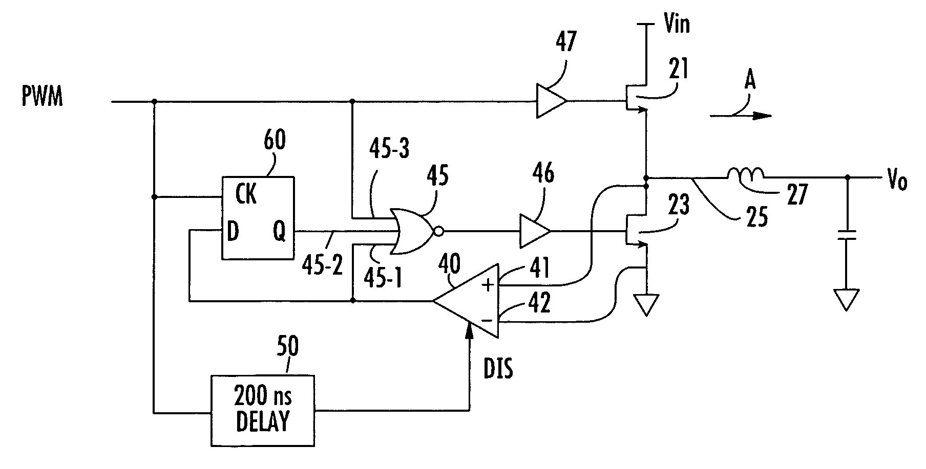
[0027] Attention is now directed to FIG. 5, which shows a modification of the buck mode DC-DC converter circuit of FIG. 2 in accordance with an embodiment of the present invention, to include a memory element that is used to selectively latch the output of the phase detector and thereby control the switching of the operation of the converter between synchronous buck mode and standard buck mode operation, in a manner that is effective to prevent boosting the voltage of the system bus. In particular, FIG. 5 shows the addition of a D-type flip-flop 60 having its D input coupled to the output of the phase comparator 40, its clock input CK coupled to receive the PWM waveform, and its Q output coupled as an additional input to NOR gate 45. As will be described below, the state of the Q output of flip-flop 60 determines whether the converter is to operate in synchronous buck mode or standard buck mode.

[0028] When operating in standard buck mode, LFET 23 is held off, so that only its body ...


PUM


Abstract

A controllably alternating buck mode DC-DC converter conducts cycle by cycle analysis of the direction of inductor current flow to decide whether to operate in synchronous buck mode or standard buck mode for the next successive cycle. For each cycle of the PWM waveform controlling the buck mode DC-DC converter, a mode control circuit examines and latches data representative of the direction of inductor current flow relative to the chargeable battery. If the inductor current flow is positive, a decision is made to operate in synchronous buck mode for the next PWM cycle, which allows positive current to charge the battery; if the inductor current drops to zero, a decision is made to operate the converter in standard buck mode for the next PWM cycle, so as to prevent current from flowing out of the battery and boosting the system bus.

Description

CROSS-REFERENCE TO RELATED APPLICATION [0001] The present application claims the benefit of co-pending U.S. Patent Application Ser. No. 60 / 591,203, filed Jul. 26, 2004, by Eric Solie et al, entitled: “Method to Prevent Boosting the System Bus When Charging the Battery,” assigned to the assignee of the present application and the disclosure of which is incorporated herein.FIELD OF THE INVENTION [0002] The present invention relates in general to power supply systems and subsystems thereof, and is particularly directed to a method and apparatus for controllably switching the operation of a buck mode DC-DC converter between synchronous buck mode and standard buck mode in a manner that is effective to prevent boosting the voltage of the system bus in the course of the buck mode converter charging a battery. BACKGROUND OF THE INVENTION [0003]FIG. 1 is a reduced complexity circuit diagram of a typical synchronous buck mode DC-DC converter architecture for charging a battery by way of a vol...

Claims


Application Information

Patent Timeline
IPC IPC(8): G05F1/613
CPCH02J7/022Y02B40/90Y02B70/1466H02M3/1588H02J7/02H02J2207/20Y02B40/00Y02B70/10
Inventor SOLIE, ERIC MAGNEJOCHUM, THOMAS A.
Owner INTERSIL INC
Why Eureka
Try Eureka