OFDM transmission system
- Summary
- Abstract
- Description
- Claims
- Application Information
AI Technical Summary
Benefits of technology
Problems solved by technology
Method used
Image
Examples
first preferred embodiment
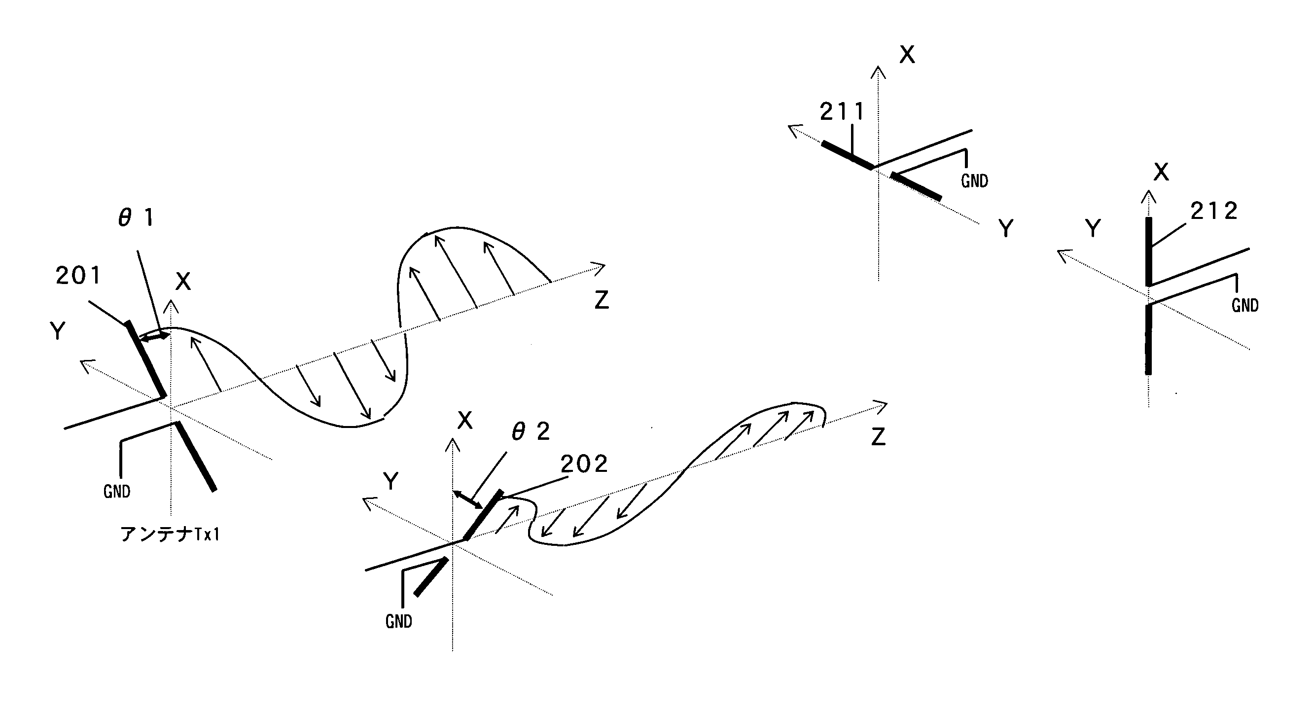
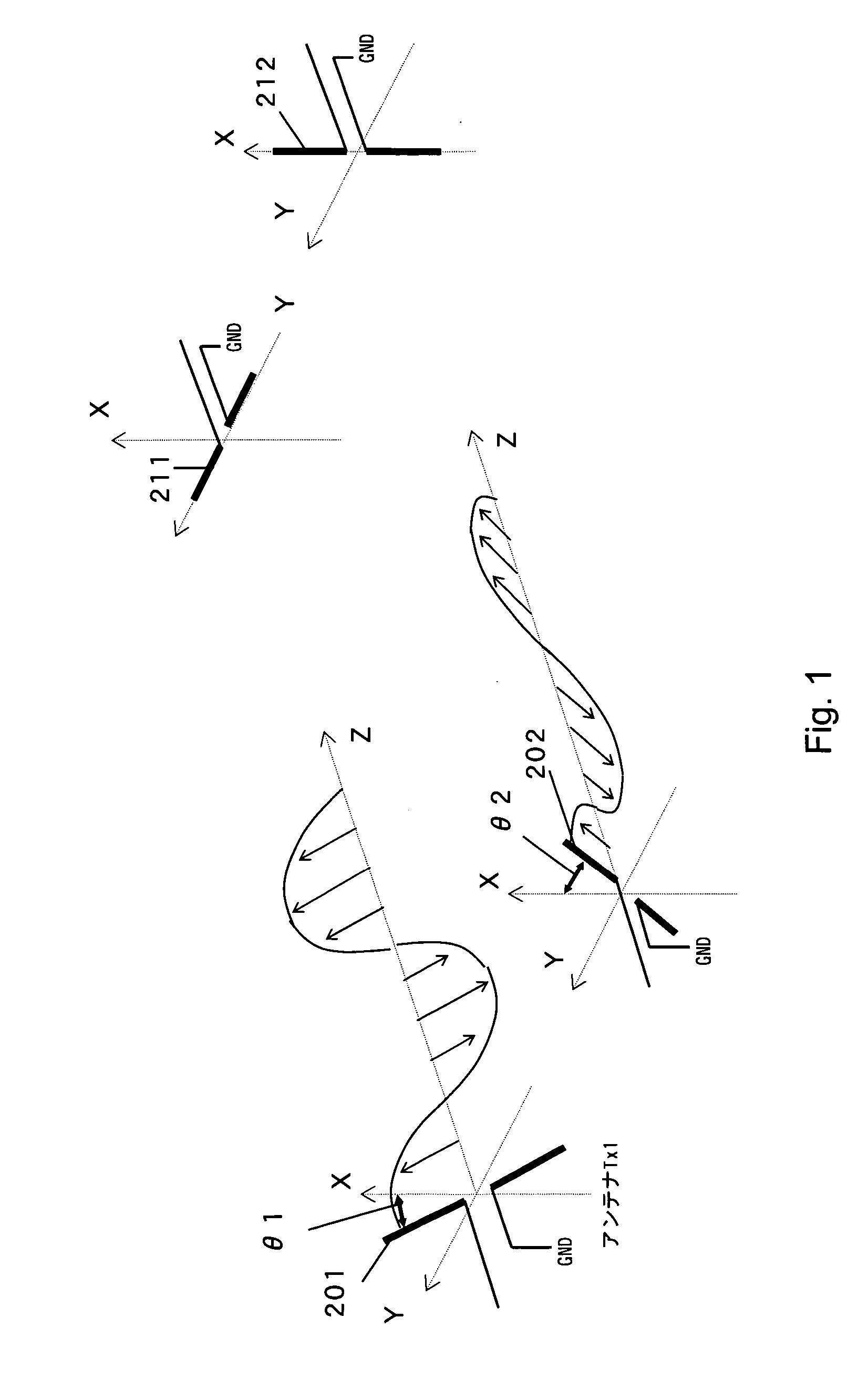
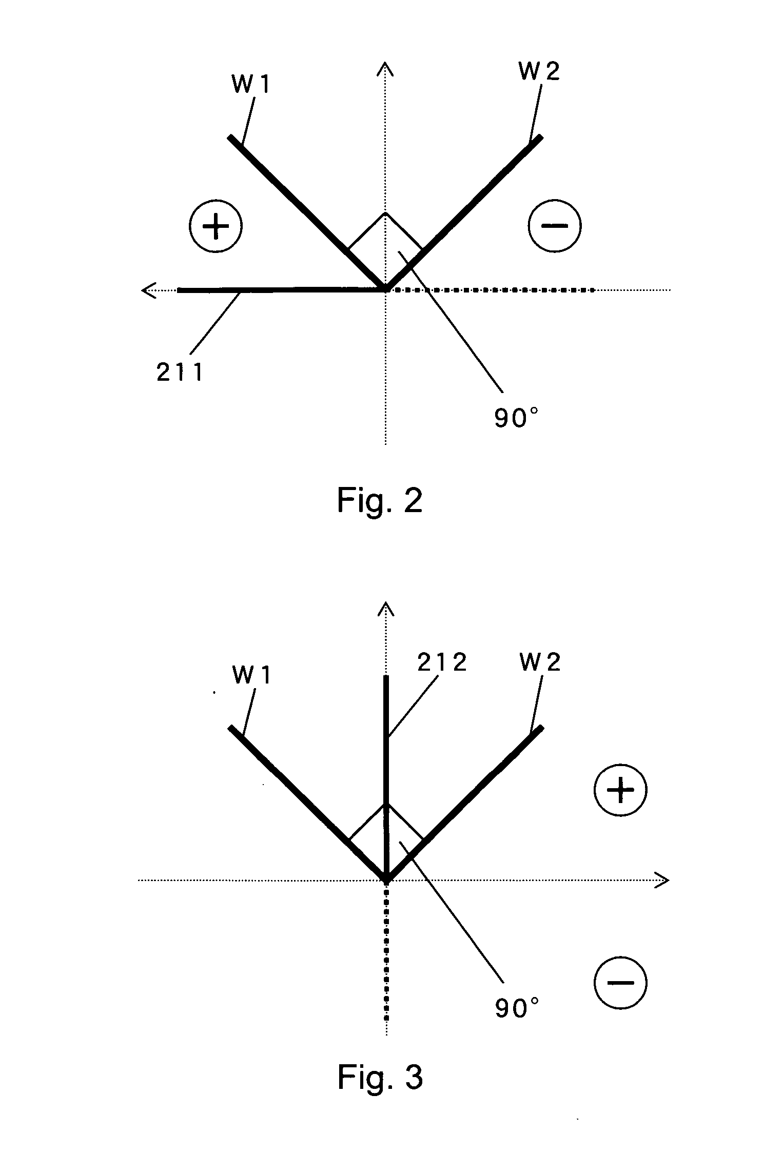
[0029] An OFDM transmission system according to a first embodiment of the present invention will first be explained using FIGS. 1 through 3.
[0030]FIG. 1 is a block diagram for describing a layout relationship among transmitting antennas and receiving antennas employed in the first embodiment of the present invention. In the OFDM transmission system according to the first embodiment of the present invention, a transmitting device is provided with two transmitting antennas 201 and 202. The transmitting antenna 201 extends in positive directions of an imaginary X axis and an imaginary Y axis on an imaginary X-Y plane and has an angle θ1 made with respect to the imaginary X axis. The transmitting antenna 201 transmits a transmit signal having a COSθ waveform. The transmitting antenna 202 extends in a positive direction of an imaginary X axis and a negative direction of an imaginary Y axis and has an angle θ2 made with respect to the imaginary X axis. The transmitting antenna 202 transm...
second preferred embodiment
[0036] An OFDM transmission system according to a second embodiment of the present invention will next be described using FIGS. 4 through 6. FIG. 4 is a block diagram for describing a layout relationship among transmitting antennas in their entirety, which are employed in the second embodiment of the present invention. FIG. 5 is a block diagram for describing a layout relationship among the individual transmitting antennas employed in the second embodiment of the present invention. FIG. 6 is a block diagram for describing a layout relationship among receiving antennas in their entirety, which are employed in the second embodiment of the present invention. FIG. 7 is a block diagram for describing a layout relationship among the individual receiving antennas employed in the second embodiment of the present invention.
[0037] In the OFDM transmission system according to the second embodiment of the present invention, a transmitting device is provided with three transmitting antennas 401...
third preferred embodiment
[0045] An OFDM transmission system according to a third embodiment of the present invention will next be explained using FIG. 8. FIG. 8 is a block diagram for describing a layout relationship among transmitting antennas in their entirety, which are employed in the third embodiment of the present invention.
[0046] In the OFDM transmission system according to the third embodiment of the present invention, a transmitting device is provided with three transmitting antennas 801 through 803. As shown in FIG. 8, the transmitting antenna 801 is located on an imaginary X axis. The transmitting antenna 802 is located on an imaginary Z axis. The transmitting antenna 803 is located on an imaginary Y axis. That is, in the OFDM transmission system according to the third embodiment, the respective antennas are placed in a three-dimensional layout relationship and orthogonal to one another.
[0047] According to the OFDM transmission system showing the third embodiment of the present invention, diffe...
PUM
 Abstract
Description
Claims
Application Information
 - R&D
- Intellectual Property
- Life Sciences
- Materials
- Tech Scout
- Unparalleled Data Quality
- Higher Quality Content
- 60% Fewer Hallucinations
Browse by: Latest US Patents, China's latest patents, Technical Efficacy Thesaurus, Application Domain, Technology Topic, Popular Technical Reports.
© 2025 PatSnap. All rights reserved.Legal|Privacy policy|Modern Slavery Act Transparency Statement|Sitemap|About US| Contact US: help@patsnap.com


